PART 4,5,6 and 7
Everything in these sections are linked so I dealt with them as one.
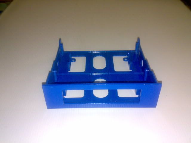
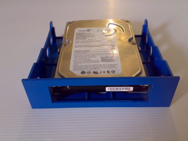
To start a painted the bay converter blue and mounted the HDD.
PART 1
PART 2
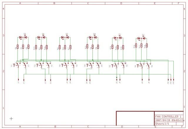
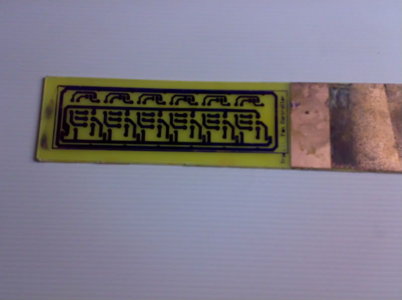
Designing a Pcb for my Fan Controller is next.I draw the circuit diagram and do the pcb layout on Eagle Cad.I use the program's Cam output to plot the pcb image straight onto the copper-clad board.This is done on my X-Y plotter using a modified pen with waterproof permanent ink.The pcb is then etched using ferric chloride in a bubble etch tank.
PART 3
PART 4
PART 5
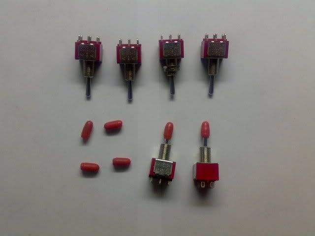
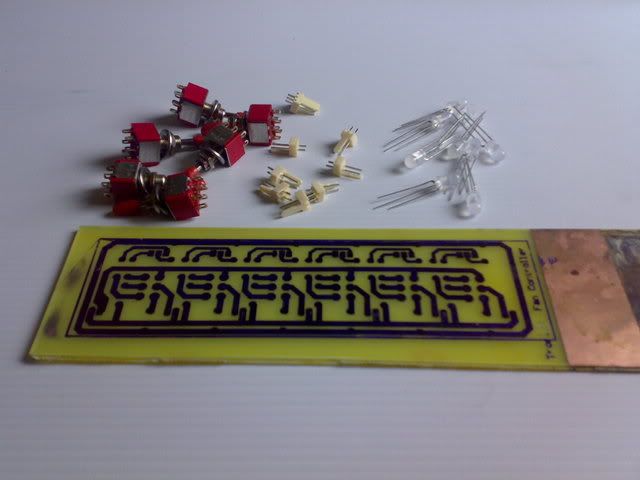
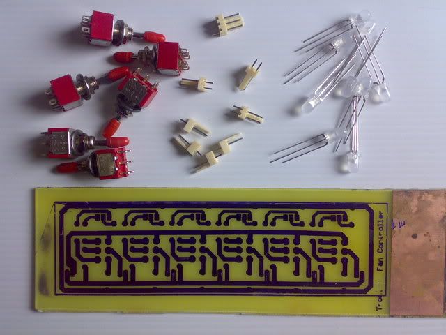
For the fan controller I used 6 x DPDT - Centre off
6 x bi-colour led's(red/green)
12 x 1k 0.25w 5% resistor's
24 x zero ohm resistors(links)
6 x 2 pin male connectors
1 x 3 pin male connector
I bring +12v,+5v and ground onto the board and switch 0v,7v and 12v to the fans.
PART 6
PART 7
PART 8
PART 9
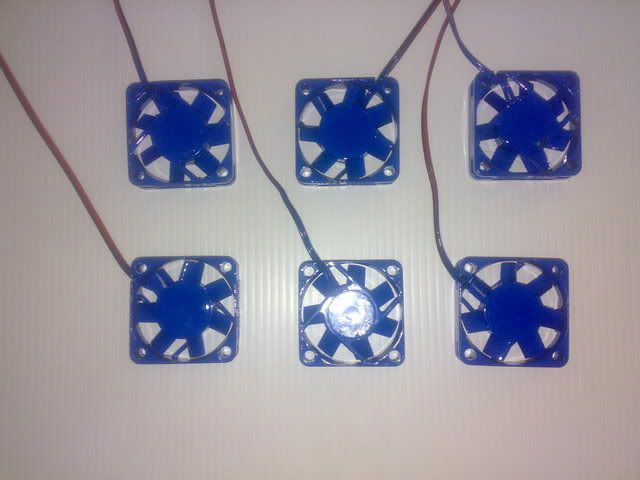
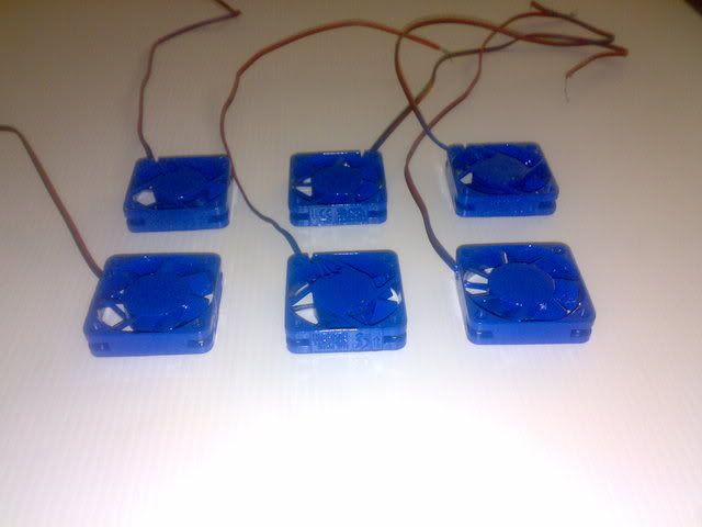
Time to paint the 40mm fans and modify the wiring.
PART 10
PART 11
PART 12
PART 13
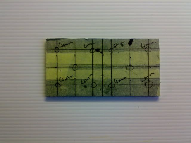
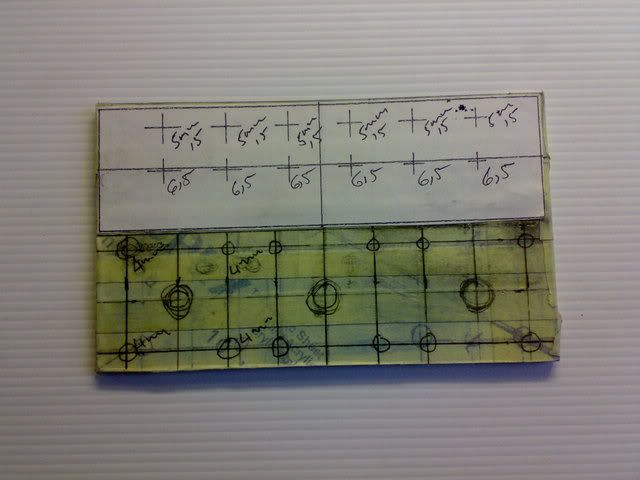
The plexi panel's masked marked and ready for drilling.
PART 14
PART 15
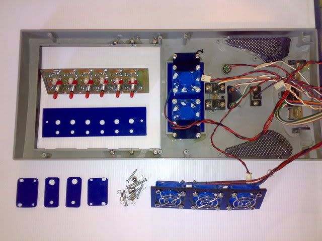
Everthing ready to be fixed to the back of the case front panel.Metal stand-off's were epoxied to the case to a mounting with bracketd and screws.
PART 16
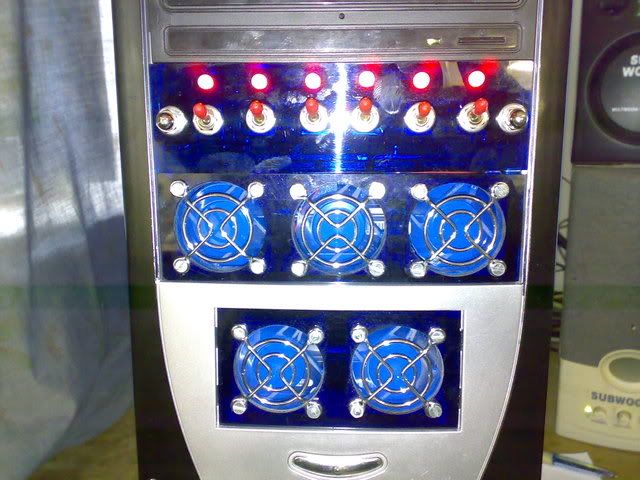
Off - 0v no light
PART 17
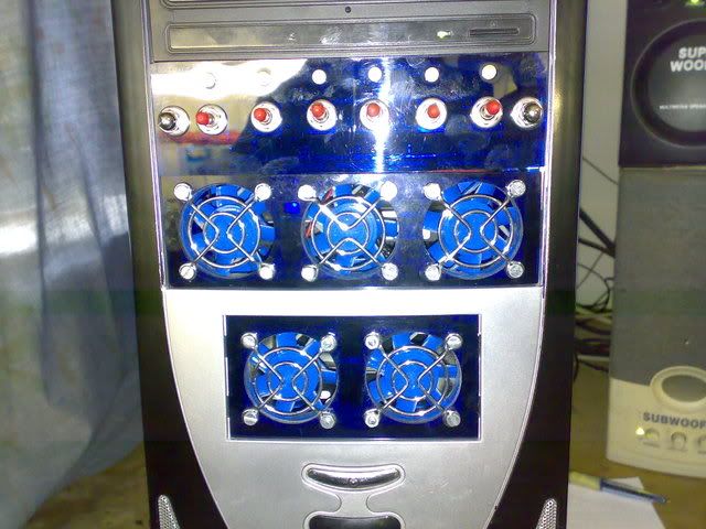
On - 7v green led's
PART 18
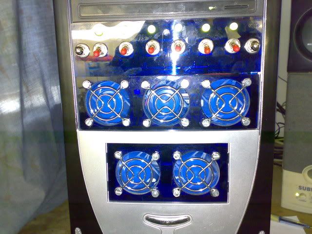
On - 12v red led's