 | ||
|
||


|
|||||||


| Water Block Design / Construction Building your own block? Need info on designing one? Heres where to do it |
 |
| Thread Tools |

 04-29-2003, 10:16 PM
|
#1 |
|
Cooling Neophyte
Join Date: Apr 2003
Location: USA
Posts: 96
|
I have been pimping this idea around a couple of other forums & BigBen2k suggested that I try here...so here it goes.
The top is solid, with the "barbs" machined right in. The only tough part is the center inlet, with it being round on top & the cross on the bottom, with the transition between the 2 shapes happening along the full length of the inlet. Thats what wire EMD's are for. It is planned to have a 1/2 inlet & 2 3/8 outlets. The top will be anaodized alum to save $$$, & the bottom out of copper. Base thickness of the bottom is planned to be .093 inch. The base will start out at 1/4", the the pocket machined down. The "fins" are right now are set .06 down from the top of the block...I couldn't decide weather to make them flush or not. The plan is for them to be .040 (1mm) wide & the channels being the same width. The actual heigth of the fins is my biggest thinking point at the moment, right now the are set at .100" or so. . The idea came alot from Cathar's white water block, the most major mod being the inlet. My thinking is that a taper will allow for a smoother flow & hopefully better results that a immediate transisition from round to oval ( or cross ). There lies the challenge, tho. The only machine that is capable of making a cut like this is a wire EDM, which are not the fastest machines in the world. A cut like this would take 45min/ 1 hour. However, I have another idea that might work as well but I could cut on a mill, & that would be the inlet being a cone shape on the top to a certain depth & then I could conjure up some of my programming skills to taper out the cross on the back side. Even simpler would be to run a drill point down & the go to the cross. I think I will call it the "X-BLOCK"     Thanks A bit about me....I am a have been working as a machinist/programmer/network admin for way too long now. I am fortunate enough to have a boss that does not mind me doing "G jobs" on my own time. My biggest problem is finding the time. [edit] shit...looks like I already posted in the wrong forum...shit again. Mods move as you wish [/edit] Last edited by Zymrgy; 04-29-2003 at 10:22 PM. |

|

|
|
04-30-2003, 12:16 AM
|
#2 |
|
Cooling Neophyte
Join Date: Feb 2003
Location: New Zealand
Posts: 4
|
Very good design you've got there
 Only got 2 things to point out that youve probably already thought of; im thinking that the water flow will be a bit restricted at the points below? 3 channels (only outlined 2 each side - oops) meeting at 1 point can't be good for flow. Perhaps sacificing some fin area for more space at the edges would be a good idea? I also find the tapered inlet to be a sound theory, just as long as you taper for the entire length of the inlet, having the smallest part of the taper as the opening. Other than that, it sure would be a good performer! Last edited by Tar Man; 04-30-2003 at 12:33 AM. |
|
|
|
|
04-30-2003, 05:40 AM
|
#3 |
|
Responsible for 2%
of all the posts here. 
Join Date: May 2002
Location: Texas, U.S.A.
Posts: 8,302
|
Thanks for stopping by, Zymrgy.
Tar man: I think you've got the flow direction reversed: it's a center inlet. |
|
|
|
|
04-30-2003, 07:39 AM
|
#4 |
|
Cooling Savant

Join Date: Dec 2002
Location: Malta
Posts: 495
|
How about taking an idea from Ben's Block ?
 If I were you, i would not leave the spot under the intlet "empty". As I said, I would either do what Ben did (sorry not did, is doing) in his block, i.e. a + shaped fin in the middle or otherwise I would include some type of cone shaped fin. Maybe Ben could explain to you better than I am. Am I in the wrong track or not??
__________________
So the bullet proof vest aint a $hit when d laser is pointed to your head Kid |
|
|
|
|
04-30-2003, 07:43 AM
|
#5 |
|
Cooling Savant
Join Date: Dec 2002
Location: Malta
Posts: 495
|
this is what i meant. add the red fin. Sorry for my paint skills

__________________
So the bullet proof vest aint a $hit when d laser is pointed to your head Kid |
|
|
|
|
04-30-2003, 07:52 AM
|
#6 |
|
Responsible for 2%
of all the posts here.
Join Date: May 2002
Location: Texas, U.S.A.
Posts: 8,302
|
What Balinju is trying to say is, use flow seperators. It'll help seperate the flow nicely, instead of letting the flow break up over the top of the fin.
Also, you might want to extend the fins into a point, because a liquid that traverses a sudden rise/drop in channel size, is going to be more restricted than in a smoother transition. Someone pointed me to a HS that would be perfect, to make a block like this. Heck if I had the time, I'd give it a shot. Nice work, very nice work. |
|
|
|
|
04-30-2003, 04:27 PM
|
#7 |
|
Cooling Savant

Join Date: Jun 2001
Location: Desert City in California
Posts: 631
|
Don't wanna be a stickler, but this thread may get better attention if it were posted int hte correct section.
BrianW
__________________
Water Cooled Inwin Q500 (Dual Rads: Rad1 = DTEK Pro Core | Rad2 = Blick Ice Estreme, Hydor L30, Dangerden Maze2, Bay Res Typhoon Reservoir, 1/2 " DD Tygon Thick Wall Hose). Flow: Res, Pump, CPU watervlock, Y into both rads, both rads into res independently. Athlon XP 1800+ (@ 1731 - 150mhz fsb.), on a Asus A7N266-c, and a Radeon 9000 *waiting for RMA'd Saphire 9800 ultra from Newegg) |
|
|
|
|
05-01-2003, 05:38 PM
|
#8 |
|
CNC Beyatch

Join Date: Aug 2001
Location: Tulsa Spell it backwards
Posts: 721
|
that is a very very nice rendering. Nice cad work.
I will leave the base alone and focus on the top of the block. you say you want the fittings machined into the top of the block. Do you have any idea how thick the top peice is going to have to be to make that? and with all the extra machine time involved to make it. That and you will need a really long endmill, which will give you deflection. But that is no problem. I dont really think the intergrated hose barb idea is worth the extra machine time involved. When drilling and tapping takes only a fraction of the time.
__________________
Creator of the Spir@l Block Longest post ever http://forums.procooling.com/vbb/showthread.php?s=&postid=43808#post43808 |
|
|
|
|
05-01-2003, 11:03 PM
|
#9 |
|
Cooling Neophyte
Join Date: Apr 2003
Location: USA
Posts: 96
|
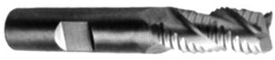
The time in making the top piece with the integrated barbs is insignificant. Really. The material would start out as 1" thick stock & the barbs are planned to be 3/4" tall. Now, a consertive estimate on removing the material start to finish would be 2 minutes, if that. Aluminium is fun to machine. "Typical" feedrates start at about 100 inches per minute, at least on the machines I have access to. I am still amazed to this day at how fast I can turn a block to a pile of chips on them. As far as deflection, a 3/4" length of cut is fine for a 3/8 carbide endmill, which would easily fit between the barbs. Funny thing is, it will take the finish tool longer to cut than the roughing tool. Most of the material would be removed with a 1/2" or 3/4" roughing tool, like this one...
 For the tapered inlet plan, I really don't think that the typical 1/4NPT barbs are an option, unless I want to make my own barbs The machine I will be using has 30HP? ( not totally sure on that rating, but it is plenty ) & a 12,000 RPM spindle. Last edited by Zymrgy; 09-02-2006 at 03:07 PM. |
|
|
|
|
05-01-2003, 11:28 PM
|
#10 |
|
Cooling Neophyte
Join Date: Apr 2003
Location: USA
Posts: 96
|
& also, to Balinju & bigben2k, is this what you had in mind?
 Now, all I did was switch the places from the "channel" & the "walls". I also added the tapered sides in, however, while not being impossable, they would be a pain in the ass to make that way, to say the least. Remember each channel is only .040 wide (1mm). Something more feasable might be to "step" the width down...this would allow me to make the fins taller as a bonus. |
|
|
|
|
05-02-2003, 07:45 AM
|
#11 |
|
Responsible for 2%
of all the posts here.
Join Date: May 2002
Location: Texas, U.S.A.
Posts: 8,302
|
Nice to have such a machine handy!
No, I meant that you should taper the perimeter of the fin pattern, not the top of the fins. Nice, very nice. |
|
|
|
|
05-02-2003, 08:00 AM
|
#12 |
|
CNC Beyatch
Join Date: Aug 2001
Location: Tulsa Spell it backwards
Posts: 721
|
well, if you got that at hand and can play with it, then by all means go for it.
See the avitar for my name, that machine I have sitting in my garage. Its a maxnc15 Open loop system. While its alot slower and feeds are alot less, Its in my garage, so I can start it and walk away. Very handy to have. I also have a large manual mill too, for doing the easy stuff. Also, if you have that machine handy, why not do it in copper?
__________________
Creator of the Spir@l Block Longest post ever http://forums.procooling.com/vbb/showthread.php?s=&postid=43808#post43808 |
|
|
|
|
05-02-2003, 08:17 AM
|
#13 |
|
Cooling Savant

Join Date: Oct 2002
Location: Malta, Mediterranean
Posts: 662
|
iMO, the circled fins are a waste of coolant as they are off the cpu.
Also, did you consider "squashing" the design? this is because AMD cpus are not square especially the Barton.
__________________
- Every great HD crash day is the day before back-up day. - My Past System - "Better to reign in Hell than serve in Heaven." - Milton, Paradise Lost. - FMZ |
|
|
|
|
05-02-2003, 08:19 AM
|
#14 |
|
Cooling Savant
Join Date: Oct 2002
Location: Malta, Mediterranean
Posts: 662
|
And yes, much of the cooling will be done through the central fins.
This is a sketch of how the CPU is orientaited WRT the Holes (socket 462). This applies to Tbred A, B and Barton.
__________________
- Every great HD crash day is the day before back-up day. - My Past System - "Better to reign in Hell than serve in Heaven." - Milton, Paradise Lost. - FMZ |
|
|
|
|
05-02-2003, 08:22 AM
|
#15 |
|
Cooling Savant
Join Date: Oct 2002
Location: Malta, Mediterranean
Posts: 662
|
This is what I meant:
Nice machines BTW
__________________
- Every great HD crash day is the day before back-up day. - My Past System - "Better to reign in Hell than serve in Heaven." - Milton, Paradise Lost. - FMZ |
|
|
|
|
05-02-2003, 11:05 AM
|
#16 |
|
CNC Beyatch
Join Date: Aug 2001
Location: Tulsa Spell it backwards
Posts: 721
|
IMO
I dont really think that extra surface area is considered a waste of space. With a thinner base plate and thinner block.
__________________
Creator of the Spir@l Block Longest post ever http://forums.procooling.com/vbb/showthread.php?s=&postid=43808#post43808 |
|
|
|
|
05-02-2003, 12:13 PM
|
#17 |
|
Cooling Savant

Join Date: Feb 2003
Location: Phoenix, AZ
Posts: 193
|
How the whitewater inspires us all.
__________________
NF7-S Bios D1.8 218FSB X 11.5 1700+ DLT3C 0310 @ 2511Mhz TwinMos 2x256 PC3200 BH-5 Albatron TI4800se 310/643 3dmark 15,110 3DMark2001SE Link |
|
|
|
|
05-02-2003, 12:28 PM
|
#18 | |
|
Cooling Savant
Join Date: Oct 2002
Location: Malta, Mediterranean
Posts: 662
|
Quote:
@Zymrgy Keep your nozzle about ~45mm^2 of area. This will vary depending on the pump pressure. *edit: centre of the core
__________________
- Every great HD crash day is the day before back-up day. - My Past System - "Better to reign in Hell than serve in Heaven." - Milton, Paradise Lost. - FMZ Last edited by hara; 05-02-2003 at 01:45 PM. |
|
|
|
|
|
05-02-2003, 06:09 PM
|
#19 |
|
Cooling Savant
Join Date: Dec 2002
Location: Malta
Posts: 495
|
yes Zymrgy that is exactly what i meant
very very very ... nice machine btw, i would like to have one in my garage just as fixittt has  and also i agree with hara, make some calculations and the extra fins remove them because they could only be restring the flow of the water. You need just a little bit more than 2mm of fins or 2mm of fins on each side of the core, ie, if the core is 10x10mm, then 14x14mm of fins would be enough
__________________
So the bullet proof vest aint a $hit when d laser is pointed to your head Kid |
|
|
|
|
05-03-2003, 12:55 AM
|
#20 | |
|
Cooling Neophyte
Join Date: Apr 2003
Location: USA
Posts: 96
|
Ok, I think I am getting the gist of what everyone is getting at. That & I am getting good at modifing my fins, lol. I decided to see what it would look like if I added a cone in the middle of the thing.
 Looks pretty good....& should do something like direct the flow. bigben2k...is that what you meant by adding taper to the fins? Quote:
|
|
|
|
|
|
05-03-2003, 01:03 AM
|
#21 |
|
Cooling Neophyte
Join Date: Apr 2003
Location: USA
Posts: 96
|
Also, @ Fixittt, that would be a way sweet toy to have in a garage. nice. As far as making the top out of solid copper, well, we really don't work with much copper where I work, & none of the 1" thick stock hanging around. I am trying to make do with what we have....I can use material reminates for nothing. On alternative that I had not thought of before was making the top out of brass....but then brass is not as easy to machine as alum either.
The thing is, we send out parts for anodizing on a weekly basis. Most of those places charge a "lot" fee to do the work. So, if you want 1 part done, it costs $50. If you want 50 parts done, it costs $50. So, I could just slip my parts in for nothing. |
|
|
|
|
05-03-2003, 06:08 AM
|
#22 |
|
Cooling Neophyte

Join Date: Aug 2002
Location: Sweden
Posts: 63
|
That sure will be a neat WB, my suggestion, when u've settled on the findesign, make several bases with different thickness. That is if u have time to test them all
__________________
Asus A7N8X Deluxe, 2500+@2700MHz (13,5x200), 2x256MB TwinMOS pc3200 @ 2-2-2-11, GFFX 5900 Ultra@500/950MHz, 2x120GB Maxtor Diamondmax 9 8MB SATA raid-0, Prometeia, Logitech z-680. 20000+ 3Dmark2001 Duron 600@1521MHz RIP |
|
|
|
|
05-03-2003, 06:26 AM
|
#23 |
|
Cooling Savant
Join Date: Dec 2002
Location: Malta
Posts: 495
|
My opinion on the second design with the cone.
I thin the cone is going to be difficult to mill, when our machinist was trying to mill the cone for our water block called squirrel, he had to stop in the middle of the process cause he thought that the pin was moving while being milled. But that would be a very nice thing to have inside a waterblock another thing, just try to at least round the corners marked in red in the following picture. They cause cause some breakage of water flow.
__________________
So the bullet proof vest aint a $hit when d laser is pointed to your head Kid |
|
|
|
|
05-03-2003, 06:34 AM
|
#24 |
|
Cooling Savant
Join Date: Dec 2002
Location: Malta
Posts: 495
|
or otherwise you could also make them converge to a poing like a triangle if making them round is difficult
__________________
So the bullet proof vest aint a $hit when d laser is pointed to your head Kid |
|
|
|
|
05-03-2003, 07:59 AM
|
#25 |
|
Responsible for 2%
of all the posts here.
Join Date: May 2002
Location: Texas, U.S.A.
Posts: 8,302
|
Actually, I meant that you should taper the very end of the fins.
Cathar calculated that the optimal fin-to-channel ratio should be between 1.5 and 0.75, so as long as you incorporate that over the core, and 2mm beyond, you're all set. It looks very, very good. |
|
|
|
|
«
Previous Thread
|
Next Thread
»
| Currently Active Users Viewing This Thread: 1 (0 members and 1 guests) | |
| Thread Tools | |


|
|

All times are GMT -5. The time now is 05:05 AM.