 | ||
|
||


|
|||||||


| Water Block Design / Construction Building your own block? Need info on designing one? Heres where to do it |
 |
| Thread Tools |

 10-11-2005, 04:40 PM
|
#1 |
|
Cooling Neophyte
Join Date: Nov 2004
Location: Oregon
Posts: 14
|
Hello all,
I have been visiting this site for a long time, "ooing" and "aweing" at all the awesome custom work. I took the plunge a few weeks ago and designed my own solid brass reservoir. I'll post some updated pics of that later if anyone is interested. I am almost done designing my first waterblock for my X800XT. It will be out of copper, brass, and possibly delrin. A friend of mine used to be a machinist for an aerospace company, and has a ton of precision drills, cutters, etc. I have modeled my block in CAD, and he said he would make it for me. It consists of a silver-plated baseplate, mounted below a brass "jetplate", and followed by a delrin top-plate. I have an area that's 1.15" x 1.22" that will come in contact with the die. I have 255 holes drilled in this area. Each hole is 0.030" in diameter, and 0.030" center-to-center. My question is: Do you think this is too small of a diameter for holes? This is the smallest he could do, and I was figuring the more holes... the better the thermal transfer. Any feedback would be great. Thanks! -Ben |

|

|
|
10-11-2005, 08:54 PM
|
#2 |
|
Cooling Savant

Join Date: Dec 2004
Location: Orlando, Florida
Posts: 383
|
You could skip the brass "jetplate" and have him machine it out of delrin to save on weight. It would make things a little more simple to. There is a limit to how small you want the holes. At a certain point the surface tension of water will prevent any sort of penetration into the hole. I don't know what this dimension is, though LongHairedGit (sp?...too lazy) has a great deal of knowledge in such areas and should be able to provide insight.
|
|
|
|
|
10-11-2005, 11:54 PM
|
#3 | |
|
Cooling Savant
Join Date: Aug 2004
Location: Granite Bay, CA
Posts: 105
|
Quote:
I would be interested in seeing your brass reservoir. I designed my external cooling rig and the res is the only part I'm not happy with. I can't find anything on the market that is laid out the way I want. I am replacing my current res with a clear round acrylic res I am drilling and tapping new holes for 9/16-18 DD high flow barbs in the positions I want. I started to make one out of a "Carlon" Marine electrical junction box, but decided to do this one 1st. I have tried a lot of ideas with this Carlon(a dense type of plastic-it feels pretty nice)res, Just haven't decided which of a number of different placements for the baffle yet. A brass res would be too sweet. I found a trick brass adjustable sight level indicator at Graingers-let me know if you would like to see a photo of it. Good luck with your block.
__________________
ASUS Maximus II Formula, E8600@4050, OCZ 2x2GB PC2 8500@5-5-5-18, Vista 64, GTX 280@693/1508/2566, Audigy 2, PC P&C 750, ASUS DVD R/RW, Velociraptor 300, Raptor 74, Storm rev2, modified Laing DDC, modified HL BI2 Extreme, 7/16 ID Tygon, modified DD res, PC ICE, TT liquid temp monitor |
|
|
|
|
|
10-12-2005, 07:10 AM
|
#4 |
|
Cooling Savant
Join Date: Aug 2005
Location: uk
Posts: 400
|
The hole size is equivalent to the g7 so it should be fine. However H/D (plate height to jet diameter) should not be more than 15 and ideally needs to be more like 1 for jet based cooling to work. This is a pressure tradeoff as well so its abit more complicated than that because cooling performance increases slower than pressure drop. The center to center distance is roughly optimal but it is preferable to use something like the extend jets that are used in the G seris as it allows water to flow away from the plate. More distance might be advisable to aid this. Bear in mind that the jet plate may deform in use unless it is thick. Porting the jet holes is a v good idea as well.
I am current developing a high performance block that you could use but need to turn a seris of sketches into a proper design. Should work better than a block of this type but it is primarly designed to be easy to machine so might be abit simple for your uses. Its high pressure drop as well but thats a design variable that i could change (trade per lpm perfromance for less p drop). I just need to write it up. |
|
|
|
|
10-12-2005, 09:46 AM
|
#5 | ||
|
Cooling Neophyte
Join Date: Nov 2004
Location: Oregon
Posts: 14
|
Quote:
  Quote:
 As for keeping the weight down, the analysis I've done on this block in the CAD program tells me that it weighs less than the solid brass DD MAZE4GPU. I'd like to leave the jet plate as a brass piece... mainly cause I don't trust delrin to not warp or something. Anyway, I'll check some things out and post some pics of my block. I've gotta still put the o-rings in... then it should be done. Thanks for the feedback so far! As for keeping the weight down, the analysis I've done on this block in the CAD program tells me that it weighs less than the solid brass DD MAZE4GPU. I'd like to leave the jet plate as a brass piece... mainly cause I don't trust delrin to not warp or something. Anyway, I'll check some things out and post some pics of my block. I've gotta still put the o-rings in... then it should be done. Thanks for the feedback so far!
|
||
|
|
|
|
10-12-2005, 10:38 AM
|
#6 |
|
Cooling Neophyte
Join Date: Nov 2004
Location: Oregon
Posts: 14
|
OK, I measures the height of the plate and the jet diamter. The height of the plate is 0.0625" and the diamter of the holes are 0.030". So I'm looking at a ratio that's roughly 2:1. That sound good?
|
|
|
|
|
10-12-2005, 04:04 PM
|
#7 |
|
Cooling Neophyte
Join Date: Nov 2004
Location: Oregon
Posts: 14
|
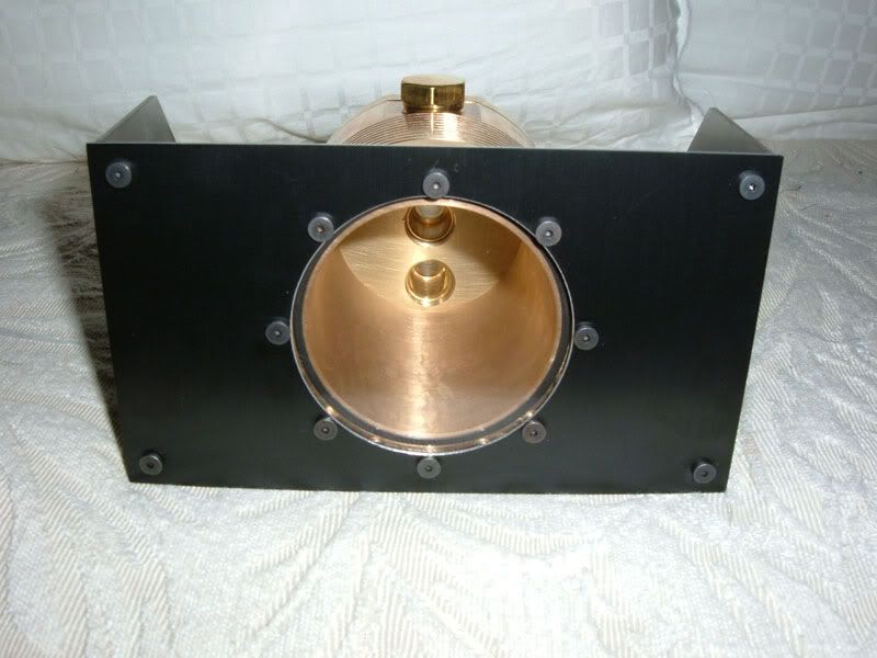
Finished.
 The only thing I'm concerned about is the hole diameter... but hey. Anyway, here are a couple pics: The only thing I'm concerned about is the hole diameter... but hey. Anyway, here are a couple pics:Any feedback? I've already got material and the machinist is gonna start on this for me soon. Can't wait, hopefully this thing will perform pretty well. :shrug: -Ben Last edited by 3Tripnip; 10-14-2005 at 08:41 PM. |
|
|
|
|
10-14-2005, 07:17 AM
|
#8 |
|
Cooling Savant
Join Date: Aug 2005
Location: uk
Posts: 400
|
hexagonal pattern would be better as it allows a higher jet density. I'm worried you perhaps to many jets to be useful. Porting the jet holes and having less jets will probably improve perfromance for a set pumping power.
The distance im talking about for h/d is distance between cooling plate and jet exit. I would be worried about possible plate deformation and its effects on perfromance though at small spacings. |
|
|
|
|
10-14-2005, 10:39 AM
|
#9 |
|
Cooling Neophyte
Join Date: Nov 2004
Location: Oregon
Posts: 14
|
Hmmm... never heard of porting. I'll do some more research on it. Thanks!
Last edited by 3Tripnip; 10-14-2005 at 08:40 PM. |
|
|
|
|
10-15-2005, 05:37 AM
|
#10 |
|
Cooling Savant
Join Date: Aug 2005
Location: uk
Posts: 400
|
What i mean is make the entrance holes a smoother profile. Tell your machinist to add as big a chamfer on the inlet as he can. If he puts them in a hexagonal pattern he can get a bigger chamfer which is good. My guess is for a good porting the head recovery will be noticeable.
|
|
|
|
|
10-15-2005, 09:41 AM
|
#11 |
|
Cooling Savant
Join Date: Feb 2003
Location: Willmar MN/Fargo ND
Posts: 504
|
if you use a #0 center drill, it will probably be the right diameter or smaller diameter with a nice 60 degree chamfer, I think thats what cathar's machinsts do with his(or at least it looks like it)
Jon |
|
|
|
|
«
Previous Thread
|
Next Thread
»
| Currently Active Users Viewing This Thread: 1 (0 members and 1 guests) | |
|
|

All times are GMT -5. The time now is 11:54 AM.