 | ||
|
||


|
|||||||


| General Liquid/Water Cooling Discussion For discussion about Full Cooling System kits, or general cooling topics. Keep specific cooling items like pumps, radiators, etc... in their specific forums. |
 |
| Thread Tools |

 11-24-2005, 01:40 PM
|
#301 |
|
Cooling Neophyte

Join Date: Mar 2005
Location: Slovenia
Posts: 94
|
Great post Orkan.
The tool was not fully sharp, anyway I think that it was not made with mill because it would take too long. Did you take any measures of pins and channels?
__________________
EK Water Blocks |

|

|
|
11-24-2005, 02:40 PM
|
#302 | |
|
Thermophile

Join Date: Sep 2002
Location: Melbourne, Australia
Posts: 2,538
|
Quote:
I said that the testbed (TTV) was. Can have the world's best sculpter. You can give him a blunt tool, but don't expect miracles, that's all I'm saying. |
|
|
|
|
|
11-24-2005, 02:45 PM
|
#303 |
|
Cooling Savant
Join Date: Oct 2003
Location: inside my computers
Posts: 113
|
Approx Pin array dimensions -
34mm x 34mm 1mm channel between the pins. |
|
|
|
|
11-25-2005, 04:32 AM
|
#304 | |
|
Cooling Savant
Join Date: May 2004
Location: Portugal
Posts: 179
|
Quote:
About the HS mechanical issue, could it be practical and efficient to use a IHS like this one below and then to secure it in place using the same kind of lever system that Intel has for the socket 775? 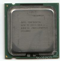 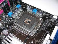
|
|
|
|
|
|
11-25-2005, 07:12 AM
|
#305 | ||
|
Cooling Savant
Join Date: Sep 2003
Location: Vallentuna, Sweden
Posts: 410
|
Quote:
Quote:
Lee, I like this arrangement for many reasons but there is one problem with the vertical hole for the temperature sensor that I think is insurmountable. Basically it means that there is a large uncertainty in the vertical location of the point that is measured which makes it impossible to use the data for any kind of modelling. The vertical shaft will have a different temperature gradient than the copper around it and the position of the sensor is uncertain. Compare this to a horizontal hole. The gradient (in the vertical direction ) is the same as the surrounding copper, the measured temperature is some kind of average of the temperature of the hole surfaces and does not vary by more than a tiny amount along the length of the hole. In the case of the vertical shaft the same applies, namely that the measured temperature is some kind of average of the shaft surfaces, except that the temperature is varying hugely along these surfaces and a small "position error" would have a large impact on the measured temperature. Edit: I have drawn something to try and explain explain this, I believe it is very important that you don't do this. The holes should be horizontal. Always. Their effects (heat shadowing) can be modelled, the effects in a vertical shaft can't. Last edited by Incoherent; 11-25-2005 at 07:32 AM. |
||
|
|
|
|
11-25-2005, 08:11 AM
|
#306 |
|
CoolingWorks Tech Guy Formerly "Unregistered"
Join Date: Dec 2000
Location: Posts: 2,371.493,106
Posts: 4,440
|
even with the horizontal locating is a bit of a question mechanically
- I guess the 'effective' location could be back calculated with some accuracy and, as has been discussed here before, need to quantify the clamping force (with load cells ?) load cells will reveal mounting hardware issues clearly and provide repeatability more and more sophisticated, how many still in ? (not to be negative, but these inevitably become so complex than none continue) |
|
|
|
|
11-25-2005, 08:21 AM
|
#307 | |
|
CoolingWorks Tech Guy Formerly "Unregistered"
Join Date: Dec 2000
Location: Posts: 2,371.493,106
Posts: 4,440
|
Quote:
since the CPU/socket/mobo will have to be replicated (as part of the source) to mount a sink or wb that locates off the mobo, there is a lot of hardware involved; other systems let the mobo float between the chassis and the sink, and it will be a brand new exercise for BTX |
|
|
|
|
|
11-25-2005, 10:20 AM
|
#308 | |
|
Put up or Shut Up

Join Date: Dec 2001
Location: Spokane WA
Posts: 6,506
|
Quote:
|
|
|
|
|
|
11-25-2005, 10:26 AM
|
#309 |
|
Cooling Savant
Join Date: Oct 2003
Location: inside my computers
Posts: 113
|
You'd think it would be sawed... but it looked milled to me.
|
|
|
|
|
11-25-2005, 11:06 AM
|
#310 | |
|
Cooling Savant

Join Date: Sep 2002
Location: Cincinnati, OH
Posts: 229
|
Quote:
Yes, I agree with what you are saying. I did a quick calc and for a 14mm^2 cross-area with 100W load thru copper, I get ~1.3 deg C per mm... not so good. "Today" I am leaning towards a one-piece heat die and heatspreader with two or three temp sensors located in the sides of the die to generate a heat flux curve and that use an extrapolated temp value for calculating the WB dT and C/W. I also like the idea of a rectangular die (maybe 14 x 16mm?) since that seems to be the direction more of the newer CPU's are going in. (I know, much controversey there...  ) )Bill: Yes, I have considered integrating a load cell underneath the die and creating the upwards force by regulating the air pressure to a small cylinder instead of a spring. Considered "clamping" the WB under test and then pushing the die/heat spreader up with a known force. This is great for analytical testing but removes the variability of specific mounting hardware that the end user will have to deal with. As you said though, complexity often leads to no action... |
|
|
|
|
|
11-25-2005, 11:14 AM
|
#311 | |
|
Cooling Savant

Join Date: May 2003
Location: Wakefield, West Yorkshire, UK
Posts: 486
|
Quote:
|
|
|
|
|
|
11-25-2005, 11:37 AM
|
#312 | |
|
Cooling Savant
Join Date: Jan 2004
Location: london, england
Posts: 416
|
Quote:
hmm - just a (lateral) thought, but could you overcome this by using a spring to push upwards on the sensor in the vertical hole? |
|
|
|
|
|
11-25-2005, 12:51 PM
|
#313 | |
|
Cooling Neophyte
Join Date: Nov 2005
Location: Over There
Posts: 37
|
Quote:
I haven't seen a constant force spring that's designed for compression, only tension, but that doesn't mean they don't exist. You might be able to rig some kind of crazy lever system to get compression. I'd go that route before looking at using pneumatics. |
|
|
|
|
|
11-25-2005, 02:28 PM
|
#314 | |
|
Cooling Savant
Join Date: Sep 2003
Location: Vallentuna, Sweden
Posts: 410
|
Quote:
It is one of my concerns with the TTV which experiences a similar effect, but they are mitigated somewhat by a very concise description on how to affix the TC to ensure a good contact and thus ensure that the temperature measured is in fact the temperature at the point expected. I am reasonably happy with the TTV concept, although it is not the way I would have done it. In working with Intel I have found that they generally know what they are doing. |
|
|
|
|
|
11-25-2005, 02:38 PM
|
#315 |
|
Cooling Neophyte
Join Date: Apr 2005
Location: South California
Posts: 26
|
Is it just me.. or are many online retail stores not selling the Storm any more? And at the same time, the price seems to have increased.
This leads me to the conjecture that Swiftech is end of lifing the Storm. |
|
|
|
|
11-25-2005, 06:21 PM
|
#316 | |
|
Cooling Savant
Join Date: Oct 2003
Location: inside my computers
Posts: 113
|
Quote:
|
|
|
|
|
|
11-26-2005, 02:27 PM
|
#317 |
|
Cooling Savant

Join Date: Jan 2003
Location: Sydney, Oz
Posts: 336
|
Here's a good point: the Apogee will work well as a TEC block too.
__________________
Long Haired Git "Securing an environment of Windows platforms from abuse - external or internal - is akin to trying to install sprinklers in a fireworks factory where smoking on the job is permitted." (Prof. Gene Spafford) My Rig, in all its glory, can be seen best here AMD XP1600 @ 1530 Mhz | Soyo Dragon + | 256 Mb PC2700 DDRAM | 2 x 40 Gb 7200rpm in Raid-0 | Maze 2, eheim 1250, dual heater cores! | Full specifications (PCDB) |
|
|
|
|
11-26-2005, 03:42 PM
|
#318 |
|
Cooling Savant
Join Date: Oct 2003
Location: inside my computers
Posts: 113
|
the pin array is only 34mm^2 ... that enough cooling area to work on a 50mm^2 TEC like a 200+ watt?
|
|
|
|
|
11-27-2005, 10:09 AM
|
#320 |
|
Cooling Neophyte

Join Date: Nov 2005
Location: England, UK
Posts: 4
|
I don't know if you guys are aware of this thread on [H], slightly worrying :/
|
|
|
|
|
11-27-2005, 10:50 AM
|
#321 | |
|
c00ling p00n

Join Date: Jun 2002
Location: L.A.
Posts: 758
|
Quote:
__________________
*:-.,_,.-:*'``'*:-.,_,.-:*'``'*:-.,_,.-:*'``'*:-.,_,.-:*'``'*:-.,_,.-:* E6700 @ 3.65Ghz / P5W DH Deluxe / 2GB 667 TeamGroup / 1900XTX PC Power & Cooling Turbo 510 Deluxe Mountain Mods U2-UFO Cube Storm G5 --> MP-01 --> PA 120.3 --> 2x DDC Ultras in Series --> Custom Clear Res "Artificial intelligence is no match for natural stupidity." 1,223,460+ Ghz Folding@Home aNonForums *:-.,_,.-:*'``'*:-.,_,.-:*'``'*:-.,_,.-:*'``'*:-.,_,.-:*'``'*:-.,_,.-:* |
|
|
|
|
|
11-27-2005, 03:16 PM
|
#322 | |
|
Responsible for 2%
of all the posts here. 
Join Date: May 2002
Location: Texas, U.S.A.
Posts: 8,302
|
Quote:
From my perspective, the IHS is mounted in a way to spread the applied mounting pressure between the core area and the rim of the IHS. In what proportion, we do not know. To estimate it, we'd need all of the measurement of *everything* (core, substrate, IHS), then we'd need to know how thick the seal is on the rim of the IHS, then we'd need to know how hard it(seal) is; then we could quantify how the mounting pressure is spread out. It's a nightmare. The load cell idea is great, but I'd rather use the heat dies straight out (10 by 10 and 14 by 14mm), no IHS, and apply an offset for temperature calculations (if we can ever figure them out), which should make up for the missing IHS in the test bench. Anyone disagree? Alternatively, we could put on a free-floating IHS, and use mounting pressure similar to bare core mount specs (i.e. 24 to 30 lbs), but that assumes that that's the actual pressure. |
|
|
|
|
|
11-27-2005, 05:47 PM
|
#323 |
|
Put up or Shut Up
Join Date: Dec 2001
Location: Spokane WA
Posts: 6,506
|
Hummm,
If the IHS temp is all the TTV uses then how is that different than the die temp of a die sim? The only thing that bothers me about the IHS is the heat spread/flux. Without putting dozens of probes all over the IHS we really don't know how much of the IHS is being cooled/warmed. Therefor guessing a dimension is useless without the needed data from dozens of calibrated probes of insane resolution. I say **** it and will be using a die sim. 
|
|
|
|
|
11-27-2005, 06:06 PM
|
#324 |
|
Cooling Savant
Join Date: Sep 2002
Location: Cincinnati, OH
Posts: 229
|
Remember this? Even though a heat spreader is used, the heat die (core) size still plays a major role...
 Post #57 by Groth http://forums.procooling.com/vbb/sho...3&page=3&pp=25 |
|
|
|
|
11-27-2005, 06:18 PM
|
#325 | |
|
Put up or Shut Up
Join Date: Dec 2001
Location: Spokane WA
Posts: 6,506
|
Quote:
More reasoning IMO to stick with die sim. |
|
|
|
|
|
«
Previous Thread
|
Next Thread
»
| Currently Active Users Viewing This Thread: 1 (0 members and 1 guests) | |
|
|

All times are GMT -5. The time now is 04:31 AM.