 | ||
|
||


|
|||||||


| Water Block Design / Construction Building your own block? Need info on designing one? Heres where to do it |
 |
| Thread Tools |

 01-17-2006, 04:47 PM
|
#26 | ||
|
Cooling Savant

Join Date: Jan 2006
Location: VA
Posts: 129
|
Quote:
 They're 1/16th" deep and I will be making them with a modified milling bit so that the bottom edges will be rounded and a cone will be left in the center. Quote:
Brass would be fine, I would prefer Delrin though. What would respond best to epoxy with stainless steel? Last edited by Captain Slug; 01-17-2006 at 05:37 PM. |
||

|

|
|
01-18-2006, 08:23 AM
|
#27 |
|
Cooling Savant
Join Date: Feb 2003
Location: Willmar MN/Fargo ND
Posts: 504
|
Why dont you get some brass tube? You could possibly solder that into place.
Brass would be best for epoxying the tubes in I think. I doubt you'll be able to turn those little tiny peices of tube down to a smaller diameter. I know you wont make that 52 holes that size in stainless, it wouldnt be fun! and the bottoms of those cups, leave them flat, you dont want to help the water get out of there, you want the most turblience. Jon |
|
|
|
|
01-18-2006, 05:07 PM
|
#28 | ||
|
Cooling Savant
Join Date: Jan 2006
Location: VA
Posts: 129
|
Quote:
Would it be better to get brass rod that's 3/64 OD then drill our the center or get 1/16" OD tubing and then sand the outside down to 3/64? If only I could remember what my uncle taught me about casting brass cartridge shells... Quote:
Last edited by Captain Slug; 01-18-2006 at 05:21 PM. |
||
|
|
|
|
01-18-2006, 05:33 PM
|
#29 |
|
Cooling Savant
Join Date: Sep 2002
Location: ohio
Posts: 140
|
Probably putting them in a lathe rather than drill press would be better, but if I had a choice I think I'd be inclined to buy smaller OD rod and drill out the center.
|
|
|
|
|
01-18-2006, 05:46 PM
|
#30 |
|
Cooling Savant
Join Date: Aug 2005
Location: uk
Posts: 400
|
the base of the cup holes needs to flat smooth and square. Putting a cone in the middle will lower performance and putting a radius on the edge in this case is not a good idea (this is counter to normal design principals.)
I'll try this weekend and write up something in the wiki about jet impingement and how it works but these days i dont seem to have the time for things like that so i make no promises and whatever i have time for this weekend is going to be very bried and probably a bit crap. Key thing to remember is that the spacing of the plate and the nozzle exit is exceptionally important and given you nozzle size is going to be very small i have concerns about the construction. I would think the MAX you would want to make it is 3 times the nozzle diameter so good luck! Above about 9 to 15 times and its not jet impingement. The walls of the holes need not be that deep but it requires some serious number crunching and fluid mech knowledge to know what "not that big" means. The characteristic length scale is the nozzle exit diameter so maybe 10 times that is a good guess. |
|
|
|
|
01-18-2006, 05:58 PM
|
#31 |
|
Cooling Savant
Join Date: Jan 2006
Location: VA
Posts: 129
|
Alright. Looks like brass rod will be easiest and will allow me to get these dimensions for each cup.
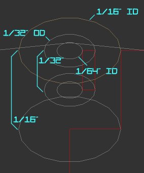 This should have the optimal nozzle-exit-size to distance-to-cup-base ratio based on what I've read. But all of these dimensions are variable now that I can simply drill out the hole size I want in whatever rod size I want. The next rod size up is 3/64. I would also like to thank everyone for their feedback. I'm learning way more than I had anticipated. Last edited by Captain Slug; 01-19-2006 at 12:29 AM. |
|
|
|
|
01-19-2006, 08:12 AM
|
#32 |
|
Cooling Neophyte
Join Date: Oct 2005
Location: Mission, KS
Posts: 12
|
This is a really neat design. I like how you have the water flowing from the inlet chamber to a 360deg outlet chamber. Very clever. Can't wait to see an actual design. PM me if you want good 3d rendered previz.
|
|
|
|
|
01-20-2006, 07:25 PM
|
#33 | |
|
Cooling Neophyte

Join Date: Jun 2004
Location: Denver, CO
Posts: 29
|
Quote:
They aren't that expensive (think Chinese) and, unless you are magic, your plan on drilling/fixturing/refixturing/more drilling, etc. is not gonna work, especially at the sizes/tolerances we're talking about here. Seriously....rotary table. |
|
|
|
|
|
01-21-2006, 01:06 AM
|
#34 |
|
Cooling Savant
Join Date: Jan 2006
Location: VA
Posts: 129
|
The channel bends and pits are the same bit size and will most likely be done using a programmable mill to save time and effort. Then the lathe work begins, and after that I'll mill the channels.
The mounting holes could be done with a bridgeport or pre-drilled to a smaller size with the programmable mill. |
|
|
|
|
05-16-2006, 03:56 AM
|
#35 |
|
Cooling Savant
Join Date: Jan 2006
Location: VA
Posts: 129
|
Thread revival!
I'm not sure if I really want to experiment with jet impingement right now and I'm being a cheapskate so I'm trying to revise my design minus the nozzles and pits. So I'm just going to go with a slightly simplified version that I can make from a 2x2x0.1875" copper scrap. Fin height is 3.16mm and base thickness is 1.5mm (blame inches). 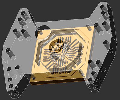 I'm going to be doing all the work myself on a manual mill so I think I'm going to start with something relatively simple. I'll be able to do the 45-degree channels by simply making a mounting block that the base bolts onto. Both barbs will be 3/8" NPT x 1/2"ID tubing. I have the tools, the time, and the materials. I just need to get back to wrapping my head around this since I've been away for a few months. |
|
|
|
|
05-16-2006, 11:29 AM
|
#36 |
|
Cooling Neophyte
Join Date: Jun 2004
Location: Taiwan
Posts: 55
|
looks fun, watch out for the top cover leakage, otherwise its pretty cool
|
|
|
|
|
05-16-2006, 01:24 PM
|
#37 |
|
Cooling Savant
Join Date: Jan 2006
Location: VA
Posts: 129
|
Here's the coverage on a 1.25" IHS
 I'll be using a 1-1/2" ID 1-5/8" OD Red-Orange Silicone O-Ring |
|
|
|
|
06-18-2006, 03:14 PM
|
#38 |
|
Cooling Savant
Join Date: Jan 2006
Location: VA
Posts: 129
|
I've decided to make this a little bit easier on myself by simplifying the machining of the block a little. The new design is a sandwhich of three parts that collectively will be easier to make. It may also alleviate the outlet concerns of the previous revisions,
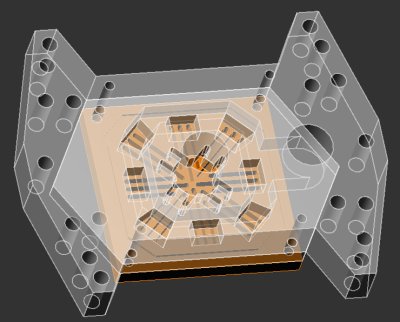  The plate in the middle will be solvent-adhered to the thick top piece. Last edited by Captain Slug; 06-18-2006 at 03:23 PM. |
|
|
|
|
06-19-2006, 02:42 PM
|
#39 |
|
Cooling Savant

Join Date: Mar 2003
Location: Hamburg
Posts: 141
|
nice design but i liked the older revisions more, just try it on a cnc then its no problem with that many bends
 . . performance should be on a level with top waterblocks ala rbx/tdx or white water. it remembers me of a little bit similar block which i did some time ago (the block on the right). Its sandblastet and polished. channels are 8x 1mm*2,5mm 
|
|
|
|
|
06-19-2006, 06:20 PM
|
#40 |
|
Cooling Savant
Join Date: Jan 2006
Location: VA
Posts: 129
|
I don't have access to CNC. All of the tooling will be done with manual equipment. I've been keeping that in mind with all of my designs so they're all possible to make with manual equipment. The newest revision could work with the older base design, but I'm unsure about being able to add the channel bends with a manual mill.
Sure this would all be much easier with CNC equipment, but I don't know anyone who would help me out for free with that. I already have the materials and free access to the manual mill. And I haven't mentioned this here yet but I'm also working on my own 1/2" ID 3/4" OD compression fittings. 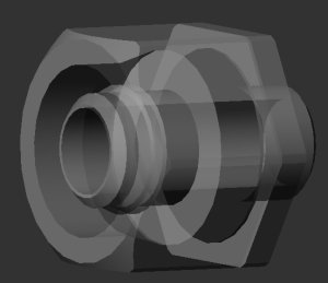 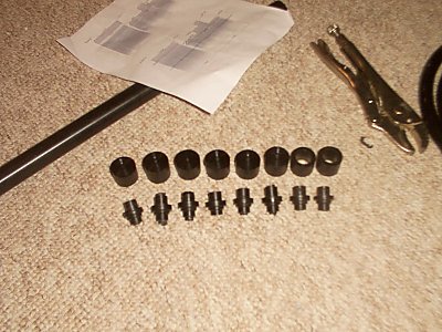 I'll do some more thinking about nozzle and channel refinements. Last edited by Captain Slug; 06-19-2006 at 06:40 PM. |
|
|
|
|
06-19-2006, 07:16 PM
|
#41 |
|
Cooling Savant
Join Date: Jan 2006
Location: VA
Posts: 129
|
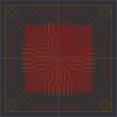
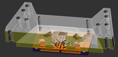
Improvement?
 My pump can handle the restriction if I can handle the machining of the base. |
|
|
|
|
06-20-2006, 08:28 AM
|
#42 |
|
Cooling Savant
Join Date: Mar 2003
Location: Hamburg
Posts: 141
|
why are you making compression fittings on your own? I thought there is a huge selection on the market of those.
The nozzle looks nice, but i believe a nozzle with only holes would perform better. I have a round chamber in the top of the block below and tried different round shaped nozzleplates. The nozzle with only holes was a little better than a nozzle whith slits like a star. In all i think the block will still be horrible to manufacture with a manual mill, but i would love to see you try it and make it like it looks as a rendering, i would like it even better if it was one of the earlier revisions (latest on page1 looks good). I have a very small CNC-mill and recently made a version of my K5 which you see in Post #39 with 2mm channels witheout bends instead of the highly restrictive 1mm ones. If you are interested i will show you pics and specs when i am finished with this two blocks. If I had some more free time i would offer you to mill the cooler on my cnc, but that is curently impossible and would also be very complex to redo your drawings in my proprietary CAD/CAM software that i could draw one or two new designs in that time. Last edited by davidzo; 06-20-2006 at 08:37 AM. |
|
|
|
|
06-21-2006, 12:35 AM
|
#43 |
|
Cooling Savant
Join Date: Jan 2006
Location: VA
Posts: 129
|
My whole loop will be using 1/2" ID 3/4" OD tubing which is not a size that compression fittings are offered for. So I'm making my own out of delrin.
I'm still hedging on whether or not to bother with jet impringement using nozzles and cups but based on your advice I will go with a drilled nozzle pattern rather than the star pattern. The star pattern was solving a machining issue that the new design no longer has. The only person I've talked to in the states about CNC work is JFettig, and I don't know what software he uses. I'm using Alibre Xpress because it's what the machine shop I go to uses and it's very easy to work with. Last edited by Captain Slug; 06-21-2006 at 12:48 AM. |
|
|
|
|
06-22-2006, 11:34 PM
|
#44 |
|
Cooling Savant
Join Date: Jan 2006
Location: VA
Posts: 129
|
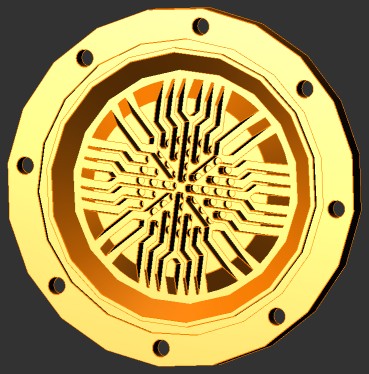
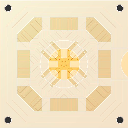
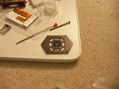
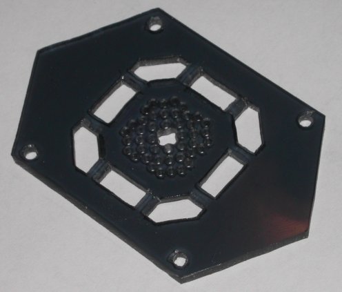
The nozzle plate is done.
Last edited by Captain Slug; 06-22-2006 at 11:50 PM. |
|
|
|
|
06-23-2006, 01:28 AM
|
#45 |
|
Cooling Neophyte
Join Date: Feb 2006
Location: Los Angeles, CA
Posts: 41
|
Hey, nicely done. Compression fittings look interesting as well - do they work as intended?
|
|
|
|
|
06-23-2006, 09:22 AM
|
#46 |
|
Cooling Savant
Join Date: Jan 2006
Location: VA
Posts: 129
|
Actually I screwed up the compression fittings. I couldn't get a working thread on them with the die blocks. So if I want to make them the way I intended them to be I'd have to start over again.
After some fiddling about yesterday I discovered that the collar nuts that I hadn't finished making for the compression fittings make some strangely effective tubing clamps. 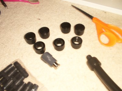 You slip the collar nut around the fitting, slide the tubing onto the fitting, then pull the collar nut onto the tubing like so. 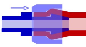 What I end up with is basically like chinese hand-cuffs. The harder I pull on the tubing, the harder the collar nut clamps the tubing to the fitting. The tubing cannot be pulled off the fitting with the collar inplace because the inner diameter of the collar nut fits the outside of the tubing so precisely that the tubing can't get over the lip on the barb. To unclamp the tubing you just push the collar nut away from the tubing. I've accidentally made a backwards compression fitting. I want to do some leak testing with these, the pump, and one block later. If I want to attempt making compression fittings again I'll have to use the lathe to add the thread to the fittings rather than trying to do it with the die blocks. Last edited by Captain Slug; 06-23-2006 at 01:56 PM. |
|
|
|
|
06-23-2006, 02:19 PM
|
#47 |
|
Cooling Savant
Join Date: Mar 2003
Location: Hamburg
Posts: 141
|
nice invention. if that works good, why not use it, it sounds very practical
nozzleplate looks good. a picture from the backside would be interesting. why is there a hole in the middle? |
|
|
|
|
06-23-2006, 09:32 PM
|
#48 | |
|
Cooling Savant
Join Date: Jan 2006
Location: VA
Posts: 129
|
Quote:
|
|
|
|
|
|
06-24-2006, 06:27 AM
|
#49 |
|
Cooling Savant
Join Date: Mar 2003
Location: Hamburg
Posts: 141
|
ah, thats it. I think it will have a noticable negative impact on performance.
There is a guy in germany who made a lot of tests about coolers with nozzles. he tried different nozzle sizes too. In his tests one bigger nozzle in the middle was always a very bad thing and did affect performance a lot. It is a little different setup so it can't be translated to every nozzlesetup, but i think in this case it is agood guess that the bigger nozzle in the middle will affect performance negatively. Read about it here (german translated with google): http://translate.google.com/translat...language_tools |
|
|
|
|
06-24-2006, 10:52 AM
|
#50 |
|
Cooling Savant
Join Date: Jan 2006
Location: VA
Posts: 129
|
Alright. Once I get some more label paper I'll make a new one.
|
|
|
|
|
«
Previous Thread
|
Next Thread
»
| Currently Active Users Viewing This Thread: 1 (0 members and 1 guests) | |
|
|

All times are GMT -5. The time now is 07:24 AM.