 | ||
|
||


|
|||||||


| Water Block Design / Construction Building your own block? Need info on designing one? Heres where to do it |
 |
| Thread Tools |

 01-14-2006, 11:47 PM
|
#1 |
|
Cooling Savant

Join Date: Jan 2006
Location: VA
Posts: 129
|
I've been wanting to design a waterblock for a while now. Regardless of whether this amounts to anything or not I'm designing what I can based around what tools I have access to (Manual Mill, Machine Lathe, Drillpress).
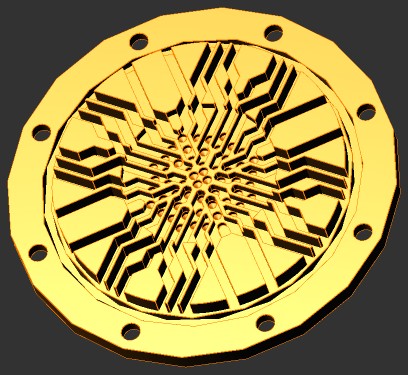
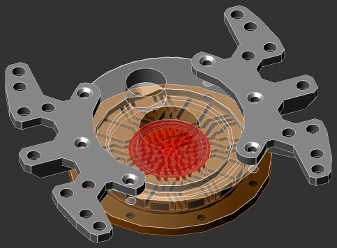
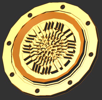
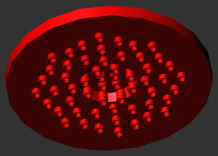
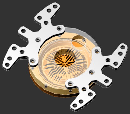
Just trying to get feedback on my design. Hit me hard because I've never done this kind of design work before and just wanted to get this concept out in the open. I've also been doing alot of reading in this forum and even though I started out hoping to do a round waterblock I came upon BigBen2k's thread thanks to nikhsub1. I found the thread very helpful and what I learned from that thread specifically lead to a dramatic change in my block design. This was the precursor that helped me figure out what I was trying to acheive. Dimensions: 2.5" Diam. x .25" thickness 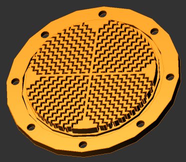 After determining what kind of pattern I wanted to use and experimenting with channel spacings I finally managed to figure out a 45-degree pattern that I'm happy with. The new design has 10 more channels, with 52 total. All at 1.4mm width. (the "fins" end up with the same width). I'll use a technique of print-out transfer normally used for PCB etching to act as a template for drilling and milling the channels. 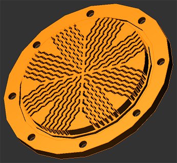 The collimater has 52 angled nozzles (13 different angles), which I'll have to drill by using a combination of an angle vice and a drill press. 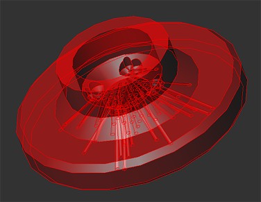 The jets in the center will have the most turbulence do to their entry angle but the center is contacted heavily by the majority of the nozzles. 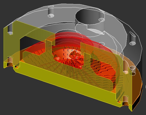 And I need to design the mounting bracket still, which will bolt flush with the top of the waterblock. 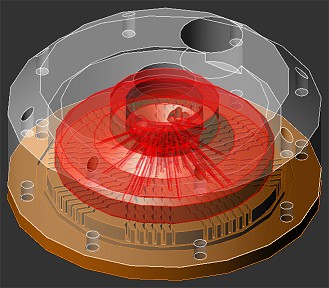 It's going to be a huge PITA to make but I'm sure I can manage it with what tools I have access to. Last edited by Captain Slug; 01-16-2006 at 07:49 PM. |

|

|
|
01-15-2006, 04:46 AM
|
#2 |
|
Cooling Neophyte
Join Date: Jan 2006
Location: North Dakota
Posts: 5
|
Looks amazing, but on a manual machine I'd guesstimate like 10 hours of machining time if you want to keep tolerances tight. Drilling that nozzle will be hell, and you'd better use fluorinert if you don't want those tiny holes clogging. Good luck!
|
|
|
|
|
01-15-2006, 09:34 AM
|
#3 |
|
Cooling Savant
Join Date: Feb 2003
Location: Willmar MN/Fargo ND
Posts: 504
|
Looks a litle bit too close to impossible
 it would be better if that jet plate was split into 2, one for the cavity and one with holes straight down otherwize its probably just gonna pour out of there very slowly. it would be better if that jet plate was split into 2, one for the cavity and one with holes straight down otherwize its probably just gonna pour out of there very slowly.Just remember that you want a concentrated cooling spot right over the core and dont need anything way the heck out there.(not much farther than 1" diameter) Im gonna say from my experience, impossible on manual machine and at least 10hrs on cnc machines. How are you liking alibre? I tried it out for about a day when I didnt know how to run it, I should take a look at it again. It might be hard going backwards from pro/e and solidworks that I am being taught here at college Jon |
|
|
|
|
01-15-2006, 01:54 PM
|
#4 |
|
Cooling Savant
Join Date: Jul 2005
Location: california
Posts: 429
|
Better off making a 4 pattern channel over 8 or 10 pattern. More headaches and work with no improvements in anything.
The middle plate is almost impossible to line up the nozzles correctly with manual work. Plus, its pointless making the accel nozzle in a circular pattern because most dies are rectangular. Have the accel plate into a single large colum of 3-4 nozzles with each row at the same angles. You still get the sweeping arch idea but its easier to mill. Easier if you cut out the center dividers and make them into channels. Design an accel plate with cross pattern like aquaextreme mp blocks. |
|
|
|
|
01-15-2006, 04:27 PM
|
#5 | |
|
Cooling Savant
Join Date: Jan 2006
Location: VA
Posts: 129
|
So I shouldn't worry about making so many individual channels and concentrate on the center more? I'll try to simplify the design some more and the remaining channels could simply be branched off from the main channels. I think I've figured out a way to have the nozzles a simple set of vertical countersunk drilled holes.
Quote:
|
|
|
|
|
|
01-15-2006, 04:39 PM
|
#6 |
|
Cooling Savant
Join Date: Aug 2005
Location: uk
Posts: 400
|
Need a nice fat 90 hole for confined jet impingement to really work.
I remain sceptical on the channels back pressure. Classical theory says every 90 turn adds a back pressure of 0.5*rho*v^2. So a nice squiggly line could be painful. Classical theory is wrong in this case but still as a ball park number it does look nasty. The shorter length of some channels worries me as well as flow would prefer these over the central longer channels. Possibly leading to recirculation of flows in the channels. The nozzles wont work very well in those channels as they are too deep and letting the flow spread out more is generally a good idea. Jets hitting a plate at an angle is complicated but may improve heat transfer under certain conditions. |
|
|
|
|
01-15-2006, 06:18 PM
|
#7 |
|
Cooling Savant
Join Date: Jan 2006
Location: VA
Posts: 129
|
New base pattern
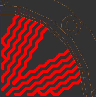 This will allow me to make all of the nozzles vertical as well as near the center. Should some of the channels have branches, or not? Or should all of them have branches? And bobo's reply adds yet another question. Should the "squigglies" be confined to just the center and the remaining length of the channels be made straight? Last edited by Captain Slug; 01-15-2006 at 06:29 PM. |
|
|
|
|
01-15-2006, 07:40 PM
|
#8 |
|
Cooling Savant
Join Date: Jan 2006
Location: VA
Posts: 129
|
I'm starting over on the pattern after alot of thinking about what has been said so far. One step forward and two steps back...
Last edited by Captain Slug; 01-15-2006 at 08:21 PM. |
|
|
|
|
01-16-2006, 02:05 AM
|
#9 |
|
Cooling Savant
Join Date: Jan 2006
Location: VA
Posts: 129
|
Okay. I messed up some of the previous design by milling the channels smaller than I intended to. I fixed this as well as trying to implement all of the suggestions put forth. These base designs have 1.6mm channels and 1mm fins and all of the channels should theoretically have nearly indentical resistance.
I do however have two patterns to pick between. 16 nozzles with branching 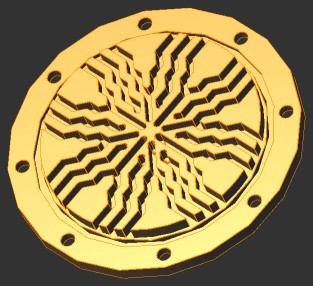 16 nozzles with no branching 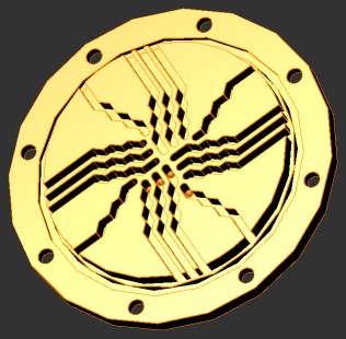
|
|
|
|
|
01-16-2006, 02:31 AM
|
#10 |
|
Cooling Savant
Join Date: Feb 2004
Location: Dunedin NZ
Posts: 735
|
its gone from overly complicated to still complicated but not even (ie, the die will not be cooled evenly)... It seems like you're making this hard on yourself for the express purpose of being so (its gonna take some work to get that right on a manual mill).
I'm all for design for the fun of it, but realistically you're throwing a dart at a wall blindfolded and expecting to hit a pin prick... the difference between block designs is extremely small, hard to measure even with the 'best' measuring equipment - im going to assume you don't have access to this gear, so at the end of the day, WHATEVER you decide to do may or may not work, and you will have no way to prove it... when you're using no maths or theory to figure out your block design, and have no ACCURATE way to test blocks, it starts getting mighty 'ballpark'-ish. I assume you know this already, though. Just to be clear, im not being a 'downer' and completely cynical here, its good fun experimenting like this (as many here have, myself included) - but if you dont have the gear to test etc, it might be an idea to start out with a few simple designs with varying dimensions, and test them in the best way you can, then test them. You can combine concepts etc then, and get an idea of what the best way to go is. Do you have any test gear? how are you going to evaluate your final design? Remember, an extremely simple cross milled block with the correct dimensions will perform very close to the complicated block you're making now - channel widths, height, restriction, base thickness etc on well designed blocks are not happy coincidences, they're made like they are for a reason, so someone designing and making a block using maths can make something extremely simple that may well wop the pants off what you're making now... Once again, this isnt an insult etc, I just want to know the direction you're heading in. These changes you're making can make or break a design - one simple change can gain 0.5 degrees, but done incorrectly (channel width, depth, dimensions, relations, WHATEVER) can just as easily lose 0.5 degrees... its swings and roundabouts, without numbers or prototypes, these changes may or may not help, and when your design is as complicated as it is, using a manual mill, perhaps designing from a different perspective might save some headaches.
__________________
Hypocritical Signature I tried to delete: Procooling: where scientific principles are ignored because big corporations are immune to mistakes and oversights. |
|
|
|
|
01-16-2006, 10:20 AM
|
#11 | |
|
Cooling Savant
Join Date: Jan 2006
Location: VA
Posts: 129
|
  Quote:
Last edited by Captain Slug; 01-16-2006 at 07:51 PM. |
|
|
|
|
|
01-16-2006, 03:19 PM
|
#12 |
|
Cooling Savant
Join Date: Jul 2005
Location: california
Posts: 429
|
Look at the MCW5002 and apogee and especially WhiteWater. Very simple but effective. complicated doesn't mean better cooling.
Milling that last one will be a ball buster. The walls are so thin and adding bends will make it hard not cut throuigh a wall. You have a decent design idea in the center. So keep the middle design but simplfy it with straight channels. The block will still look wickedly complicated and still be hard to mill wuth the tight tolerances & forget cutting all the channel on the perimeter of the block. It just reduces flow and gives no improvement in cooling. Just remove all the metal on the ouside. http://www.cooling-masters.com/forum...showtopic=2993 |
|
|
|
|
01-16-2006, 03:35 PM
|
#13 |
|
Responsible for 2%
of all the posts here. 
Join Date: May 2002
Location: Texas, U.S.A.
Posts: 8,302
|
Nice, agressive!
Check out the nozzle design for Radius; simpler, and feasible. |
|
|
|
|
01-16-2006, 03:42 PM
|
#14 | ||
|
Cooling Savant
Join Date: Jan 2006
Location: VA
Posts: 129
|
Quote:
Quote:
 I'll try the design without the bends in each channel next. |
||
|
|
|
|
01-16-2006, 04:21 PM
|
#15 | |
|
Cooling Savant
Join Date: Jan 2006
Location: VA
Posts: 129
|
Quote:
Last edited by Captain Slug; 01-16-2006 at 07:51 PM. |
|
|
|
|
|
01-16-2006, 09:29 PM
|
#16 |
|
Responsible for 2%
of all the posts here.
Join Date: May 2002
Location: Texas, U.S.A.
Posts: 8,302
|
Capillary tubes are very restrictive; you might want to look into that before pursuing that route.
|
|
|
|
|
01-17-2006, 12:50 AM
|
#17 |
|
Cooling Savant
Join Date: Jan 2006
Location: VA
Posts: 129
|
Yeah, I'm torn between wanting a relatively low-restriction block or one that's overkill.
The pin-cup and fin combination is quite appealing. Either way the drill pattern will add alot of turbulence with only mild restriction. |
|
|
|
|
01-17-2006, 01:19 AM
|
#18 |
|
Cooling Savant
Join Date: Jul 2005
Location: california
Posts: 429
|
The latest one isn't bad. I like the channel-fin and drill cup idea. Just keep chugging and rolling out revisions.
|
|
|
|
|
01-17-2006, 01:35 AM
|
#19 |
|
Cooling Savant
Join Date: Jan 2006
Location: VA
Posts: 129
|
This is where the design stands at present. The fins are 0.25" high and the nozzle array is going to be an optional insert (I have to redo the drill pattern).
 Would there be any real performance advantage to having multiple outlet barbs (2 or 4)? The center inlet at present is 1/2" NPT to allow for a much higher ID tubing (or smaller if that's what you want for some weird reason) and the outlet is 1/4" NPT. |
|
|
|
|
01-17-2006, 02:53 AM
|
#20 |
|
Cooling Savant
Join Date: Jan 2006
Location: VA
Posts: 129
|
The stainless steel jet nozzle disc will press-fit into the center of the block and be held down by the top. The nozzles are made from 1/16th" OD capillary tubes with 0.0325" ID. All but the upper 1/8" of the nozzles OD will be milled down to 0.0425 OD to fit into the matching cups in the base
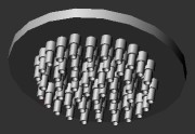 52 outlets total, and yes it will be super restrictive. But it is an optional part. 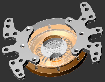
Last edited by Captain Slug; 01-17-2006 at 03:07 AM. |
|
|
|
|
01-17-2006, 06:26 AM
|
#21 |
|
Cooling Savant
Join Date: Sep 2003
Location: Vallentuna, Sweden
Posts: 410
|
I like it.
Now make it. It's possible but it isn't going to be easy. |
|
|
|
|
01-17-2006, 01:43 PM
|
#22 |
|
Responsible for 2%
of all the posts here.
Join Date: May 2002
Location: Texas, U.S.A.
Posts: 8,302
|
Better. Looks promising now.
|
|
|
|
|
01-17-2006, 03:15 PM
|
#23 |
|
Cooling Savant
Join Date: Jan 2006
Location: VA
Posts: 129
|
The single 1/4" NPT outlet is kind of small and restrictive so I'm going with 2 outlets.
|
|
|
|
|
01-17-2006, 03:52 PM
|
#24 |
|
Cooling Savant
Join Date: Jul 2005
Location: california
Posts: 429
|
Looks wicked. You had exactly what I had in mind with the perimeter. You have a good outside channel with a good sweeping bevel into it.
Straight channels would make it easier to mill but the bends make it unique. Are there going to be small cups or deep cups or any cups? |
|
|
|
|
01-17-2006, 04:23 PM
|
#25 |
|
Cooling Savant
Join Date: Feb 2003
Location: Willmar MN/Fargo ND
Posts: 504
|
Latest one looks quite a bit better,
one outlet will be plenty good, the most restriction will likely be in the jets(its where you want it). Im sure a regular 1/4" npt 1/2" hosebarb wont be a restriction to worry about. -edit- hold on, stainless steel insert? have you ever machined stainles sst? just go with brass or even plastic. why press fit? Jon |
|
|
|
|
«
Previous Thread
|
Next Thread
»
| Currently Active Users Viewing This Thread: 1 (0 members and 1 guests) | |
|
|

All times are GMT -5. The time now is 08:03 AM.