 | ||
|
||


|
|||||||


| Testing and Benchmarking Discuss, design, and debate ways to evaluate the performace of he goods out there. |
 |
| Thread Tools |

 03-16-2005, 01:32 AM
|
#76 |
|
Cooling Savant
Join Date: Sep 2003
Location: Vallentuna, Sweden
Posts: 410
|
http://www.electronic-kits-and-proje...8_software.htm
ISEE DAQ software for the kit that the digital side of this DAQ is based on. It is quite OK functionality-wise but a little limited in data processing power. I have not had time to set up a Labview reader, but that is the plan longer term, that and moving to 16bits, I'll probably use one of the National instruments DAQs. |

|

|
|
03-16-2005, 04:03 AM
|
#77 |
|
Cooling Savant

Join Date: Mar 2003
Location: notts uk
Posts: 408
|
Incoherent, I have one of the 3118 kits and sucsessfuly put it to gether. I have tried getting it to monitor the volts through a 10k POT so i can adjust the volts but in the software it never changes. If i remove the power the software then shows a drop down to 0v.
Could you do a simple 3118 for dummys guide like me ? All i want to do is data log my cpu , vga , water in , water out and case temp. I dont need to be as precise as your system just to get a good idea of whats going on. I have 100k bead thermisters for probes left over from a joystick port temp reader project will they be ok.
__________________
Folding , Folding , Folding ! |
|
|
|
|
03-16-2005, 05:57 AM
|
#78 | |
|
Cooling Savant
Join Date: Sep 2003
Location: Vallentuna, Sweden
Posts: 410
|
Quote:
How are you wiring the pot? This might be stupidly obvious but, One end should be at +5V, the other at ground (0V) and you should monitor the voltage at the wiper. The 100k bead thermistors should be fine. Put them each in series with 40k resistor a between the +5v and 0v with the thermistor closest to the +5v and monitor the voltage at the connection. The curve will look something like the attachment. To reduce the linear temperature range increase the resistor value. |
|
|
|
|
|
03-16-2005, 09:23 AM
|
#79 | |
|
Cooling Savant
Join Date: Mar 2003
Location: notts uk
Posts: 408
|
Quote:
 I dont have any 40k resistors how would i use the pot ? at the moment i put the 100k thermistor on the center of the pot and then to the 3118. all i get is a wave and the amplitude increases when i touch the thermistor. I am going to look though this thread again i am sure i saw something like this in there. (edit) i put the thermistor across the pot 5v and the output and it works ok. I tried running the power of the pc psu and a switch mode psu but they are both the same.
__________________
Folding , Folding , Folding ! Last edited by leejsmith; 03-16-2005 at 09:46 AM. |
|
|
|
|
|
03-16-2005, 10:20 AM
|
#80 | |
|
Cooling Savant
Join Date: Sep 2003
Location: Vallentuna, Sweden
Posts: 410
|
Quote:
Wired the way you have it your range is limited, you are not using the full resolution that you can achieve. If its a 100k pot wire it as attached, set it at half way and do not touch it. Then you can start thinking about calibrating. You will find that you can change the value by adjusting the pot, it might feel like a way to calibrate it but it is not, it is just going to destroy the linearity of your readings. |
|
|
|
|
|
03-16-2005, 11:37 AM
|
#81 |
|
Cooling Savant
Join Date: Mar 2003
Location: notts uk
Posts: 408
|
they are 100k and they are working ok. I have 4 sensors running but the pots need to be replaced with resistors.
thanks again
__________________
Folding , Folding , Folding ! |
|
|
|
|
03-17-2005, 05:54 AM
|
#82 |
|
Cooling Savant
Join Date: Mar 2003
Location: notts uk
Posts: 408
|
I used this website before for calibrating the thermistiors.
http://www.benchtest.com/gp_Temp3.html there is a xls spread sheet for calculating the curve of the thermistors. Will the mv reading work in place of the joystick port readings ? steinhart.xls 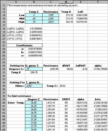 I am trying to find an old program i wrote that read from the joystick port and had the xls functions built in to.
__________________
Folding , Folding , Folding ! |
|
|
|
|
03-17-2005, 07:07 AM
|
#83 | |
|
Cooling Savant
Join Date: Sep 2003
Location: Vallentuna, Sweden
Posts: 410
|
Quote:
You just need to calculate the resistance of the thermistor at the three given temperatures from your readings. Knowing the +5v, the voltage at the thermistor (your DAQ reading) and the resistance of the series resistor, you can figure this out. (5V-Vtherm)/(Vtherm/R)=Rtherm I think. Plug in the Resistance and calibration temperature for the three temperatures and you're good to go. Good excel sheet. I did all my calculations myself but I just checked it against that sheet and it give the exact same answers for the SH-H coefficients using a slightly different method. The ISEE software control language lets you put these equations into it so you can get a calibrated temperature output directly. It's a bit buggy but works, just don't feed it divide by zero problems or it will crash. A sample might look something like this: @RES1=(5 + (@CH1/1000)*-1)/((@CH1/1000)/40000) =====> (the thermistor resistance.) @LOG1=LOG(@RES1) =====> (natural log of the resistance) @TEMP1=0.00147408 + 0.00023704*@LOG1 + 0.00000010839*@LOG1^3 =====> (A,B and C coefficients, the steinhart-hart equation ) Tags: @CH1 is ADC input, @RES1, @LOG1, @TEMP1 are analog variables There are nicer ways but this works. |
|
|
|
|
|
03-24-2005, 12:33 PM
|
#84 |
|
Cooling Savant
Join Date: Mar 2003
Location: notts uk
Posts: 408
|
i have 4 probes working using 100k@25C thermistors.
I am working on the calibration and have 2 very close but 1 is a little off this is the calibration temps  I left the probes in the hot water until they cooled down and this is the results. you can see the pink line is higher then the other 2 even though i calibrated them all at the same time. Some think not right with the pink reading they are a bit all over the place compared to the others. I wonder if i put the correct ground on this one.  I have a couple of probes from a lian li 5 1/4 drive bay temp unit. they look like they are 50k at 25C will be getting them working soon so i can use them on the cpu as the end of the probes are very thin comapred to the bead thermistors thanks for all your help i am working an a vb probram to capture the probe data and apply the curves automaticaly plus have a calibration screen.
__________________
Folding , Folding , Folding ! |
|
|
|
|
03-30-2005, 03:20 AM
|
#85 |
|
Cooling Savant
Join Date: Sep 2003
Location: Vallentuna, Sweden
Posts: 410
|
Looks good apart from the ringing. What time period are you logging at?
Try putting an RC filter on the ADC inputs, i.e. connect a 1k resistor in series with your signal line with a 0.47µF cap to ground after the resistor. This won't affect your average reading and will stabilise the signal, its a lowpass filter. The temp reading difference might be caused by errors in the real resistance of the resistor in your voltage divider (the one in series with the thermistor). Measure it if you can and adjust the value in the resistance calculation. Otherwise, if there is no major linearity problems i.e. the difference is constant, you can make small adjustments to the A coefficient value to tweak the offset away. Adding a pic of a clip. Not relevant, just don't want to start a new thread or bump this one Last edited by Incoherent; 04-11-2005 at 01:20 AM. |
|
|
|
|
04-18-2005, 03:17 AM
|
#86 |
|
Cooling Savant
Join Date: Mar 2003
Location: notts uk
Posts: 408
|
I have this working a lot better after i checked the circuits and found a couple of mistakes. Also i found that if i have a certain power supply switched on the ringing gets worse.
I have the vb program working and can calibrate the reading very easy with it just need to add things like logging to a file or spreadsheet.
__________________
Folding , Folding , Folding ! |
|
|
|
|
«
Previous Thread
|
Next Thread
»
| Currently Active Users Viewing This Thread: 1 (0 members and 1 guests) | |
|
|

All times are GMT -5. The time now is 12:00 PM.