 | ||
|
||


|
|||||||


| General Liquid/Water Cooling Discussion For discussion about Full Cooling System kits, or general cooling topics. Keep specific cooling items like pumps, radiators, etc... in their specific forums. |
 |
| Thread Tools |

 10-14-2003, 10:25 PM
|
#26 | |
|
Cooling Savant
Join Date: Dec 2002
Location: Houston, TX, USA
Posts: 221
|
Quote:
It will take some time (undetermined, but not zero time) for the thermal diode that we CAN read to heat up to as hot as it would be if the other thermal diode really was at 135 degrees C. In other words, your idea doesnt take into account the equilibrum of the system, and is thus giving a "worst case" of the difference in temperatures between the two diodes. On approach would be to use a cooling system that is BARELY inadequate, such that the temperature slowly CREEPS upward. |
|

|

|
|
10-24-2003, 06:10 AM
|
#27 | |
|
Cooling Savant

Join Date: Nov 2002
Location: portugal
Posts: 635
|
Quote:
|
|
|
|
|
|
10-24-2003, 09:18 AM
|
#28 | |
|
Cooling Savant

Join Date: Apr 2003
Location: Blackburn / Dundee
Posts: 451
|
Quote:
This point is a course vod if you have the heating break down on you like it did for me last year and you ran your air cooled system at 25* - mainly because the air temparture was hitting 0*C. ### Anyway back to the subject in hand I would like to add somehting that has allways bothered me - What's under those IHS. I've heard differing answers of mercury/air/thermal greese - and more importantly how does that affect the heat spreading ability? ~ Boli
__________________
1800+ @ 2247 (214x10.5) - STABLE, 512MB PC3700 TwinX Cosair RAM, NF7-S v2.0, GeForce3 Ti200 Parallel BIM, 120.1 Thermochill, Eheim 1048, Maze 3, Maze4 GPU, "Z" chipset, 1/2" tubing, PC-70: 5x120mm & 9x80mm fans. Internet Server & second machine (folding 24/7): 512MB DDR RAM, XP2000+ |
|
|
|
|
|
10-24-2003, 02:05 PM
|
#29 | |
|
Cooling Savant

Join Date: Nov 2002
Location: State College, PA
Posts: 338
|
Quote:
In the winter, I have my thermostats set to converse power, and I don't mind the 65*F room temps. My WC and air cooled systems both love it!
__________________
Goliath: 3.4E@3.91/Abit IC7, Maze4 (temporarily) + custom splitter to crazy 4-way watercooling parallel loop: X800XT @ 520/1280 + AC Twinplex, AC Twinplex Northbridge, Silenstar Dual HDD Cooler, Eheim1250, '85 econoline van HC + 2x120, 1x120 exhaust - polished aluminum frame panaflo L1As, 2x18GB 10K RPM U160 SCSI, 4GB PC4000. I wanna be BladeRunner when I grow up! Project Goliath - nearing completion. |
|
|
|
|
|
10-24-2003, 04:41 PM
|
#30 | |
|
Thermophile

Join Date: Sep 2002
Location: Melbourne, Australia
Posts: 2,538
|
Quote:
|
|
|
|
|
|
10-29-2003, 09:35 AM
|
#31 |
|
Cooling Savant
Join Date: Oct 2003
Location: Sussex
Posts: 109
|
are you tring to say that the UK is quasi-arctic
 I don't really know about these IHS does anyone have any links so I can read up a bit. From what you guys say isn't it a bit like adding another 1.5mm to your base plate but with the problem of an extra joint between the heat source and the coolant? Sorry if this is a stupid question it's the only way I learn |
|
|
|
|
10-29-2003, 03:08 PM
|
#32 |
|
Cooling Savant

Join Date: Apr 2003
Location: San Mateo, CA, USA, Earth
Posts: 433
|
The IHS (Integrated Heat Spreader) is a copper plate that is tinned and placed on the CPU's Core to do two functions:
1. Spread the heat and take it away from the Core an on to the heatsink. 2. Protect the core from uneven clamping pressures of heatsinks that are not mounted correctly. IHSs are found on older processors (PIIs), Pentium 4 processors and the newest offering from AMD (64bit XT right?) Someone correct me if I have been misinformed... ")
__________________
MMZ>TimeLord "Oooooooooh... that's gonna leave a mark!" |
|
|
|
|
10-29-2003, 05:03 PM
|
#33 |
|
Cooling Savant
Join Date: Oct 2003
Location: Almere, The Netherlands (Europe)
Posts: 262
|
Did anyone check the qualety of the term paste used by intell?
Artic silver seem to let the temperature drop 2 or 3 degrees compared to a normal compount. I don't think the copper is that bad, it seems to be realy thin. Bud I do wonder about the thermal paste..... Did anyone try? to replace the compount with a better one, and place the IHS back on, to avoid damaging the core? |
|
|
|
|
10-30-2003, 05:45 PM
|
#34 | |
|
Thermophile
Join Date: Oct 2002
Location: U.S.A = Michigan
Posts: 1,243
|
Quote:
A very good idea. It would be very interesting to know from any member who has removed the IHS what sort of quality TIM is used by Intel. And also as fhorst asked above: What differance in temps would there be if the Intel TIM were replaced with AS-5? ? |
|
|
|
|
|
10-31-2003, 11:22 PM
|
#35 |
|
Thermophile
Join Date: Sep 2002
Location: Melbourne, Australia
Posts: 2,538
|
 This is a picture of the base of W1zzard's Cascade showing the heat-induced oxidation of using a certain thermal paste on a P4 (with an IHS). Now one can easily notice the roughly circular shape to the oxidation pattern and how it is worse in the middle and tapers off to the edges of the pattern. One can also easily see the outline of the IHS (30x30mm in size) indented onto the block's base. A rough on-screen measurement shows that the circle is about 15mm in diameter, with the outer 1.5mm of that 15mm circle showing where the level of heat is dropping off. One can see a vague larger circle that's out 20mm in diameter, and outside of this there is no oxidation at all. So how big is the P4 die? It's a square about bang on 12x12mm in size (12.15x12.15mm I think is the near exact figure) and it sits dead in the middle under the IHS. As far as I'm concerned, this picture shows very clearly that the bulk of the heat, even with an IHS, is still focusses directly and immediately above the CPU die, but instead of being a square (like the P4 die is) it just "rounds" off the heat pattern slightly. Within 1.5mm from any edge of the die the heat induced oxidation is basically non-existent, with only very minor heat levels making it much past that 1.5mm periphery, dropping to totally insignificant levels by 3-4mm past the edge of the CPU die. This evidence is perhaps still circumstantial but I hope that it is enough to quell any nagging doubts some of you may have about just how ineffective the IHS really is at spreading the heat, and that the term "Heat Spreader" really is a bit of a misnomer when one applies strong focused cooling directly above the CPU. The Cascade's main cooling effect operates as a rough rectangle about 21x17mm in size which is still plenty large enough to optimally deal with CPU dies up to 250mm^2 in size that have an IHS on top, and CPU dies up to 350mm^2 in size if mounted directly onto the die. The ~147mm^2 P4, and the ~170-180mm^2 Athlon64's with IHS's still fall well under the Cascade's cooling "umbrella". |
|
|
|
|
10-31-2003, 11:59 PM
|
#36 |
|
Cooling Savant

Join Date: Nov 2002
Location: in my chair
Posts: 574
|
The only thing about speculation... it that it is speculation. Frankly, I would like to see a heatspreader on an Intel shaped diesim. In fact, pop one off an intel chip and place it on it. Then test using a probe.
Cathar, your doing a great job given what you have at attempting to find the answer. However, I really don't know of a good reliable, replicateable way to test blocks using the IHS. While browsing I see you on many forums. Is anyone even attempting to account for the IHS on die sims anywhere else? Its funny that procooling guys fight to the death on the tiniest of details, however the completely ignore things that will definitely effect measurements even if in a small way. Frankly the circles could be from coning it on circular lapping.. or resulting from being "punched" out while drilling the holes, or uneven application of the thermal paste. But that is just speculation. Edit: Hey.. cathar. Could you place dots around the 12X12 area of the cpu. This way we can get a good look at your example. I was unable to determine if the heat circle was outside the diameter of the cpu area... if so how much. If the circle didn't expand outside the die area that would be useful.. if it spread by 20-30% outside of the area that would be useful too. I hope you understand why I am asking, I really have NO way to determine where the chip is under that thing from the pic without going into some abstract measuring.
__________________
-winewood- Last edited by winewood; 11-01-2003 at 12:24 AM. |
|
|
|
|
11-01-2003, 12:15 AM
|
#37 |
|
Cooling Savant
Join Date: Nov 2002
Location: in my chair
Posts: 574
|
My cascade looked different when I took it off.
(all in good fun guys  ) )
__________________
-winewood- |
|
|
|
|
11-01-2003, 05:29 AM
|
#38 | |
|
Thermophile
Join Date: Sep 2002
Location: Melbourne, Australia
Posts: 2,538
|
winewood, the heat concentration deal has been simulated by a number of sources to behave in the way that I describe.
The images were intended to be more one of a pictorial respresentation of the heat concentration patterns by using what is becoming a well known reaction to heat between a certain thermal paste and copper. Quote:

|
|
|
|
|
|
11-01-2003, 08:38 AM
|
#39 |
|
Cooling Savant
Join Date: Nov 2002
Location: in my chair
Posts: 574
|
Cool! Thanks. Thats some information that is much easier to understand.
I know that the tests suggested minimal heat spreading. And I appreciate you doing the images like that. Thank you. Does the IHS actually spread the heat at all? OR is it the Cascade base spreading the heat. The only reason I even ask is... the heat could be coming strait to the copper into the cascade. The copper base could actually be spreading that heat way from the center. OR we could look at it and say, the IHS spread that heat from the center. Did you have any theories on what was doing the spreading? Which component to you contribute to the ring to the right side? If the IHS spread that heat on the right side by 30-40% beyond die, then that would suggest that one some areas the IHS can be quite effective when dealing with hot spots. (the other sides showing only 10-15% spreading over 1.5mm IHS thickness) That much spread out to the side suggests that it was VERY effective where the heat load was greatest. That places a new light on an "efficient heat spreader". Alternatively, if the right circle was a function of being spread by the cascades copper.. (perhaps the block was mounted rt side up and the heat somehow traveled that way) then the IHS not being effective in transfer would be a more realistic conclusion. I don't belive the cascade would have spread one way. Do you see why I was asking? I'm afraid I may not have been clear earlier as to my questioning. Thoughts? I think its possible that the picture may have shown the opposite conclusion.. (maybe?).
__________________
-winewood- |
|
|
|
|
11-01-2003, 08:51 AM
|
#40 |
|
Cooling Savant
Join Date: Nov 2002
Location: in my chair
Posts: 574
|
I highlighted the heat spread. Notice that something is very effective at moving the heat. 10% of die around 2-3 edges and possibly 30-40% off to right.
__________________
-winewood- |
|
|
|
|
11-01-2003, 09:19 AM
|
#41 |
|
Cooling Savant
Join Date: Nov 2002
Location: in my chair
Posts: 574
|
ALSO... consider this. The heat from the cpu that turned the thermal paste was only accounted for when it oxidized. Paste will not oxidize in the presence of just any heat, if it did the example would show oxidation over the entire application site. Do you know the temperature at which that (unamed brand) oxidizes copper like that?
Lets say its at 45C that it turns. Then the temps below 45C while not "hot" still add up to heat that must be removed. The 20C that is moving out but not turning the paste is still relevant, but unaccounted for in the oxidation example. I'm not saying these temperatures reflect reality, but since we don't know at what temp the change takes place, we do not know what heat level that change reflects.
__________________
-winewood- |
|
|
|
|
11-01-2003, 03:10 PM
|
#42 |
|
Thermophile
Join Date: Sep 2002
Location: Melbourne, Australia
Posts: 2,538
|
There is some weird light-play going on too.
Here's another image:  The patch to the right that you're referring too is still very faintly visible, but it's also apparant that it's quite secondary. |
|
|
|
|
11-01-2003, 05:49 PM
|
#43 |
|
Cooling Savant
Join Date: Oct 2003
Location: Almere, The Netherlands (Europe)
Posts: 262
|
Nice info!
Still, we can see that the IHS is transporting the heat, also that the termal compound used is transporting the heat. Question is, how well does it do that? We keep on tuning and tweaking, buy new blocks etc, just to get those extra degrees from the CPU core. So, why not try .... I'm working on some crazy setup for my WC. It will look cool when it is all attached (hopefully tomorrow), but it is a one time attachment. I'm building a water "tower", that will devide the water at the same time to the GPU, NB, Hard disk and CPU. (I did make the water holes the right size, to devide the water amound correcly (I hope)) Once i got it all connected, there is no way I can simply remove it all. (not planning on it) I think I will mod my CPU, but there is no way to tell for me if it did help any. I'll let you know the results. |
|
|
|
|
11-01-2003, 06:30 PM
|
#44 |
|
Cooling Neophyte

Join Date: May 2003
Location: Singapore
Posts: 66
|
This picture may help a bit more in the discussion.
 Its of a lapped IHS on a 3.0C which was using the previously alluded to TIM paste. The circular region is a lot more defined. (btw the CPU aint mine, shouldnt be too hard to find the thread that this was posted in if you know where to look) |
|
|
|
|
11-07-2003, 05:59 AM
|
#45 | |
|
Cooling Savant
Join Date: Oct 2001
Location: Wigan UK
Posts: 929
|
Quote:
May only help to confuse but:- Some sums Idid earlier:- http://forums.procooling.com/vbb/sho...?threadid=5416  and http://forums.procooling.com/vbb/sho...5&pagenumber=3 
|
|
|
|
|
|
11-07-2003, 11:43 AM
|
#46 |
|
c00ling p00n

Join Date: Jun 2002
Location: L.A.
Posts: 758
|
Below is a pic of my 2.6C sans IHS. You can see that the die is infact square. Bottom line is the IHS's really suck for cooling. My P4 reported the same exact temps with a TC-4, WW and the Cascade
Until I removed the IHS that is. At least on my Abit board which reads the on die reading in the CPU, my CPU now responds/acts much like all the AMD CPU's I've used. Responsive to different blocks and VERY responsive (good and bad) to proper and inproper mounts.The stock Intel TIM is not very good. When I popped the IHS off, the TIM was EVERYWHERE and way too thick and hard. People have reported a 2C drop by replacing the TIM between the IHS and the die. I can not confirm this as I will NEVER run with an IHS again, unless of cours I decide to go with a prommy or the like, and this is not likely. Cathar put it best; IHS = Idiot Handling Shield 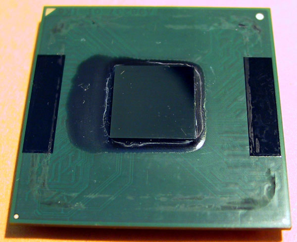
__________________
*:-.,_,.-:*'``'*:-.,_,.-:*'``'*:-.,_,.-:*'``'*:-.,_,.-:*'``'*:-.,_,.-:* E6700 @ 3.65Ghz / P5W DH Deluxe / 2GB 667 TeamGroup / 1900XTX PC Power & Cooling Turbo 510 Deluxe Mountain Mods U2-UFO Cube Storm G5 --> MP-01 --> PA 120.3 --> 2x DDC Ultras in Series --> Custom Clear Res "Artificial intelligence is no match for natural stupidity." 1,223,460+ Ghz Folding@Home aNonForums *:-.,_,.-:*'``'*:-.,_,.-:*'``'*:-.,_,.-:*'``'*:-.,_,.-:*'``'*:-.,_,.-:* |
|
|
|
|
11-11-2003, 04:08 PM
|
#47 |
|
Cooling Neophyte
Join Date: Feb 2003
Location: USA
Posts: 4
|
I would think that removing the IHS would lower temps by AT LEAST 5C or more. I don't see how it couldn't. Cathar, didn't you say that even the best TIM's accounted for at least an 8C rise in temp over ambient? The IHS is just a copper plate (and it seems an often unflat one at that) secured with a crappy tim so it's got to be making a rather significant difference. I'm anxiously awaiting my cascade so I can finally rip that damn thing off.
@ nikhsub, I'm not using the same mobo as you, I've got an epox 4pca3+ but so far having only cooled WITH the IHS, I can attest to the cpu sensor being extremely unresponsive. It responds to temperature changes rather slowly and also likes to bounce a bit. Like when I'm sitting at idle, it will usually sit there and go 40-42-40-42. My room temp is usually around 25C but when I open my window right next to the rad and let some 10C air in, it takes 5 mins before the cpu decides to drop to about 38 :shrug: |
|
|
|
|
11-11-2003, 05:09 PM
|
#48 |
|
Thermophile
Join Date: Sep 2002
Location: Melbourne, Australia
Posts: 2,538
|
Making a coarse assumption that the bulk of the heat speads at a rough 45° angle ******ds as it moves up through the IHS. This is not strictly true as it depends on what's going on with the heatsink that's attached, but it is a convenient approximation for doing rough back-of-envelope calculations like this.
This means that bulk of the heat from the 12x12mm die of the P4 roughly spreads out to a 15x15mm area at the top of the IHS. The IHS is about 1.5mm thick copper. Given the size of the P4 die the copper IHS alone presents a C/W fairly close to 0.02. (380W/mK [copper thermal conductivity through a 1x1m area] with heat flowing through a median 185mm^2 footprint area [(225+144)/2] across a 1.5mm thickness). Now let's use another rough approximation here, that being the TIM barrier. It is about 0.09C/W for a 100mm^2 size. Les will probably object here that such a value is not proven, but we're just discussing rough theory here. For the 15x15mm (225mm^2) thermal "footprint" of the heat coming out the top side of the IHS, the TIM C/W can be predicted to be around 0.04C/W (0.09 / 225 * 100). So we have 0.02C/W (cost of heat moving through the copper of the IHS) plus 0.04C/W (cost of the second TIM barrier between IHS and heatsink) for a total of around 0.06C/W for the IHS. For a 70W P4, that's about 4C which can be gained from yanking the IHS. Again, this is just a rough back-of-envelope calculation and approximation for purposes of presenting a simplified approach to calculating the thermal cost of the IHS. |
|
|
|
|
11-11-2003, 05:45 PM
|
#49 |
|
Cooling Savant

Join Date: Feb 2002
Location: Oxford University, UK
Posts: 452
|
How easy is it to remove the heat spreader?
I have an OEM 2.4C that I would quite like to play with since I will probably upgrade to a 3.2C now the prices have dropped, unless I can get a decent OC out of this chip. 8-ball
__________________
For those who believe that water needs to travel slowly through the radiator for optimum performance, read the following thread. READ ALL OF THIS!!!! |
|
|
|
|
11-11-2003, 07:12 PM
|
#50 | |
|
Cooling Savant
Join Date: Oct 2001
Location: Wigan UK
Posts: 929
|
Quote:
However do wonder why 45Degrees is chosen when this is just a particular case of the Waterloo calculations shown in my 1st graph..These too only require back-of-envelope facilities. |
|
|
|
|
|
«
Previous Thread
|
Next Thread
»
| Currently Active Users Viewing This Thread: 1 (0 members and 1 guests) | |
|
|

All times are GMT -5. The time now is 05:25 AM.